The question of the origin of the Monadnock’s Egyptian detailing was moot in late October 1884, however, for Aldis had recommended on October 20 that the project could be postponed for at least two and half years, until May 1, 1887. Although Root continued to work feverishly on the project, the Monadnock was destined to suffer a fate similar to that of Field’s office building. Both of the 13-story projects announced during the threatened height limit of 1884 failed to materialize for similar reasons: Field’s building was doomed by the fight with his former partner; Monadnock was a casualty of the battle between the real estate interests of La Salle and those of Dearborn Streets. Even though the city had seemed to have promised to complete Dearborn through to the C. & W. I. station during the summer of 1884, no construction activity on Dearborn materialized, and it was postponed again to the Fall of 1884. Aldis may have actually been trying to leverage the city into action by revealing the plans for the Monadnock at the end of April. Three months later on July 19, it was revealed that the Brookses were also ready to erect office buildings on both of the corners of the north side of Dearborn and Harrison (the eventual site of the Pontiac Building) that would have been directly across the street from the station’s originally-planned location. (Had the station been built at Harrison, these new buildings would have formed a more visually coherent complex that could have better competed with the Board of Trade area for dominance in the business district.) Aldis’ apparent public relations campaign was for naught, however, as the right-of-way of Dearborn continued to languish untouched throughout 1884.
By the fall of 1884, even Aldis had to admit defeat to La Salle Street and decided to bide his time. The construction on La Salle Street would flood the rental market in May of 1885, just as the business community expected the country to experience an economic decline if Grover Cleveland succeeded in November by becoming the first Democrat to be elected President since 1856. There would be little to be gained by adding to the glut of office space during a recession with an even taller structure on an unfinished street that wouldn’t be ready for occupancy until long after the leases had been signed for the La Salle Street buildings. Finally, after more than a year and a half of indecision, Brooks would shelve the project with a letter to Aldis on March 16, 1886, stating “There is little chance of the Monadnock Block being begun before three years.” As had been done with the Rialto Building, rumors of its impending construction would be released periodically in the coming years to bolster interest in the surrounding area, but to no avail. Monadnock would have to wait.
With construction of the C & W I station finally underway in October 1883, surely the city would now act on its promise to open up the five remaining blocks of Dearborn Street from the Post Office Square, where the construction of Dearborn had been stalled since January 1882, through to the station at Polk Street. Even in the face of the stiff competition from the construction of the new buildings along La Salle Street, the emerging boom of 1884 seemed to hold the fulfillment of the dreams of the Dearborn Street investors. Savoring a moment of hope with the city’s promise to open Dearborn to the station by the fall of 1884, the Brooks brothers’ frustrations were only reignited by the proposed height limit in March which had forced them to prematurely reveal their plans for their lot on the south side of the Post Office Square at the southwest corner of Dearborn and Jackson, thus, the mighty Monadnock Block had been conceived. At the time of its conception, however, no one would have believed that it would have a gestation period of more than five years.
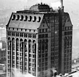
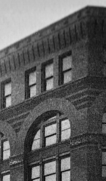
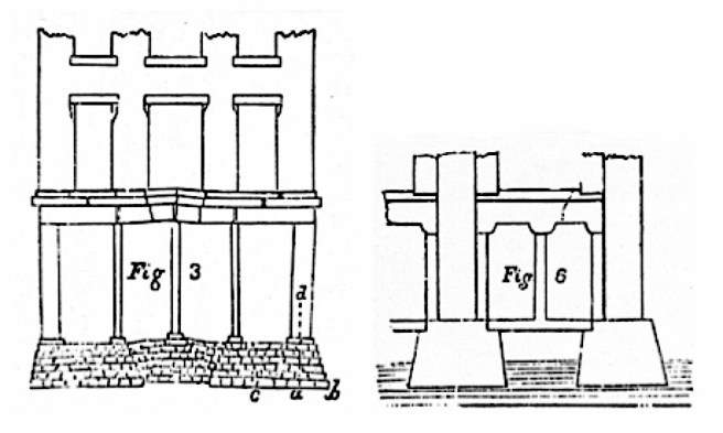
Burnham & Root, Monadnock Block, Chicago, 1884-5. Preliminary studies of the Jackson Street elevation. As the left drawing still bears the original name for the building, Quamquisset, it predates the elevation of the right. This is also evident in the building’s parapet; while the machicolated brickwork in the left design is corbelled, that in the right is flared. (Left: Saliga, The Sky’s the Limit; Right: Hoffmann, Root)
Understanding the need for haste, Peter Brooks apparently contacted Owen Aldis, as well as Burnham & Root in late March 1884, and ordered plans for a 12-story office building to be drawn up to a level of detail sufficient to secure a building permit before such legislation was enacted. On March 31, Aldis wrote to Burnham and Root: “For what price will you make such carefully prepared and studied plans for a 12-story and basement building 68 x 100, S. W. corner of Jackson and Dearborn… I mean all plans essential and necessary to get out [a] permit to build…?
At this time, Burnham & Root were deeply engaged in the design of the Rialto and Insurance Exchange with the same objective of beating the height limit. The addition of an even taller project undoubtedly began to tax the resources of their already overburdened staff and Brooks was made to wait. His impatient concern was quite evident in a letter to Aldis two weeks later, where he complained that he had not yet received any drawings for the project that in the interim he had given the Indian name, Quamquisset. As with the Montauk Block, Brooks had a preconceived aesthetic for the project: “I would request an avoidance of ornamentation… rely upon the effect of solidity and strength, or a design that will produce that effect, rather than ornament for a notable appearance.”
It took another two weeks before Brooks received Root’s first ideas for the building. Although he was “not disappointed” by the elevation, Brooks characteristically reasserted his control over Root’s ornamental proclivity in a letter to Aldis on May 6, revealing a functionalist theory that echoed Peter B. Wight’s call for a modern, Chicago aesthetic that he had articulated in his 1880 article in American Art Review (that was published in Boston):
“My notion is to have no projecting surfaces or indentations, but to have everything flush, or flat and smooth with the walls with the exception of bosses, and ornamentation of that nature in low relief, on the red terra cotta… So tall and narrow a building must have some ornament in so conspicuous a situation… [but] projections mean dirt, nor do they add strength to the building… one great nuisance [is] the lodgment of pigeons and sparrows… “
Root worked on the project during the busy summer of 1884, but judging from a letter of Aldis to Brooks written on September 16, he had once again deviated from Brooks’ prescribed aesthetic:
“I have suggested to Mr. Root that Mr. Richardson, Mr. Root and some other architects have given up in despair the problem of architectural beauty and effect, under the conditions of the modern office building, viz., great height, straight thrusts and bearings, flat surfaces, all the light attainable, low stories, and economy… Mr. Root, however, refuses to give up the problem and vows that he is back on the right track with the sketch sent you some time ago. His head is now deep in Egyptian like effects, and he declares that if he fails to make a harmonious and massive and artistic building this time, he will never build another Office Building.”
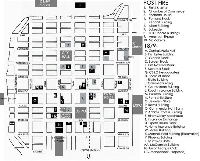
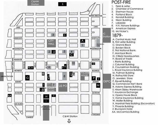
Map of Loop, 1884. (Author’s collection)
The long-awaited opening of Dearborn Street had proven to be a two-edged sword for Brooks. While it promised to increase the accessibility and traffic to his properties along Dearborn, the needed dimension for the width of the street had reduced the east/west dimension of the Quamquisset’s corner site (directly east of Jenney’s planned Union League Club) from 100′ to 66.’ With the length of the site eventually increasing to 125′ with a further purchase, Root was again confronted with the design of another thin slab office building. As Burnham & Root had also obtained the commission to design the Phœnix Building in the summer of 1884, there were actually four (including the Rialto and Insurance Exchange) such tall slab structures in various stages of design in the office at this time. A comparison among the four allows an intimate view into Root’s evolving aesthetic for the ever-increasingly taller building type.
John Wellborn Root, Comparative Study of Five Skyscraper Elevations, 1883-5. From left to right: Insurance Exchange, Phoenix, Rookery, 13-story version of Monadnock, Rialto. (Kyle Campbell)
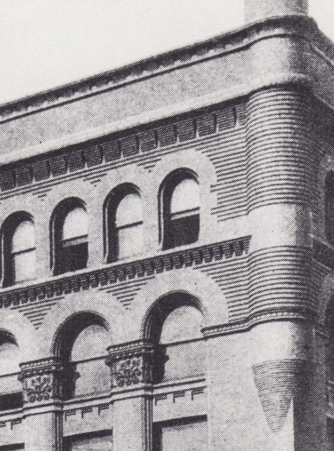
The Insurance Exchange and Phœnix Buildings have been discussed as if they were siblings, i.e., a wall with single windows versus the pier-and-spandrel language of the Rialto Building and Root’s early designs for the Monadnock Block, the new name for the Quamquisset chosen by Brooks in early 1885 in honor of the mountain in New Hampshire that was the highest mountain within easy reach of Boston. Root once again used paired windows separated by continuous piers and emphasized the corner piers to frame the elevation. He even carried over the Rialto’s original graded polychromatic scheme into the design of the Monadnock Block. Faced with four more floors than the Rialto had, Root placed an additional story in the “capital” or top layer, appropriately due to the increased vertical proportions of the taller building. The remaining three extra floors were placed in the unbroken range of pilasters that comprised the “shaft” or middle grouping of floors. This elongated the Rialto’s four-story continuous piers to seven floors in the Monadnock, including the pilasters’ lotus capitals that encompassed the eleventh floor, the tallest unbroken piers he had designed up to this point. The only significant departure from the other three slab buildings in the Monadnock’s design, outside of the obvious stylistic choices, was the location of the major entrance. Instead of placing it on the long side, Root located an entry on the short face that fronted Jackson Street and the Post Office Square.
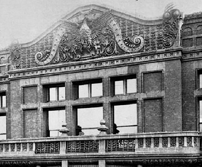
Using the “capital” or top layer of the elevation to impart a majority of the “style” to his buildings, Root simply switched the gothic crown of the Rialto to an Egyptian cornice for the Monadnock. This he detailed by subtly flaring the machicolated brickwork in the top floor to recall the capital of an Egyptian abstracted papyrus column. Donald Hoffmann has speculated the reason for Root’s choice of Egyptian detailing, specifically the papyrus plant, for the design of the Monadnock as being consistent with his desire to impart symbolic content to his buildings. As he was led to the Venetian Gothic for the Rialto because of the bridge between it and the Board of Trade, Hoffmann suggested that Root had equated Chicago’s marshy conditions with those of the Nile, as well as the origin of Chicago’s name, “wild onion place,” with a similar Egyptian plant, the papyrus.
FURTHER READING:
Hoffmann, Donald. The Architecture of John Wellborn Root. Baltimore: Johns Hopkins University Press, 1973.
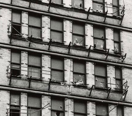
Burnham & Root, Phœnix Building. South (rear) elevation. Demolition photo taken by Richard Nickel in 1959. The windows behind the four elevators that were supported by iron skeleton framing. (urbanremainschicago.com)
While the Phœnix Building’s Jackson Street elevation didn’t score big marks for consistency, the never seen rear elevation was a prophesy of one of the options available to rationally design the elevation of a skyscraper based solely upon expressing its iron skeleton construction (there was no need of arches with the iron frame). Having studied the history of the early skyscrapers over the past forty years, I think that there was a greater interdependency than heretofore understood upon the two technologies that are always cited as having been responsible for the birth of the tall office building. Some historians, like myself, claim it was the elevator that allowed the “skyscraper principle” to blossom, while others still maintain that a skyscraper needed to be iron skeleton-framed. I am stating that it was the interdependency of these two technologies that manifested the first examples of exterior iron framing, at lease this seems to have been the case in Chicago.
George Post, Mills Building. Typical floor plan. (Gray, Elevator)
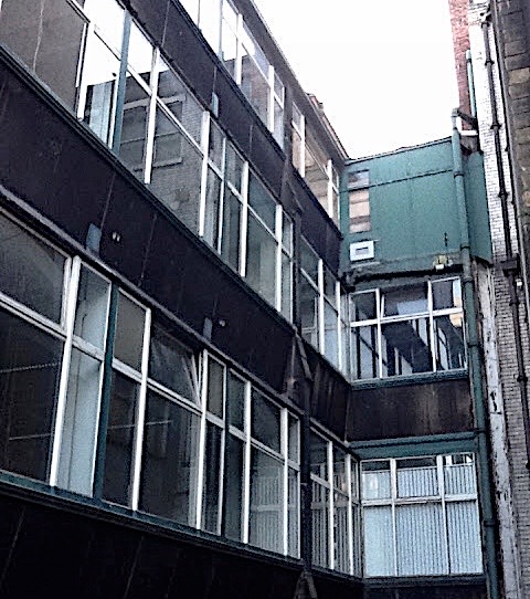
George Post. Left: Mills Building. Entrance. Note the repetitive windows in front of the elevator bank on each floor. (Online) Right: Produce Exchange. Photo of construction showing the iron skeleton framing in the light court walls. (Landau and Condit, New York)
Once again, I have already shown that it was George Post who was the first to use the iron skeleton frame in the exterior walls of post-fire buildings. This occurred in the light courts in the Mills Building and New York Produce Exchange (and most likely even the pre-fire Equitable Building: see Vol. 3, Sec. 2.12). This was simply logical because these exterior walls were not at the building’s perimeter, and therefore, were not subject to the city’s building code pertaining to thickness or construction. Therefore, Post was free to make these walls as thin and lightweight as possible. This was possible because he could still rely on the heavy exterior masonry walls to provide the necessary lateral stiffness. As these walls were not visible to the public (the Mills Building being somewhat the exception), Post had enclosed these walls with a minimum of effort and material, that also provided a maximum of daylighting.
Elevator historian Lee Gray’s research has impressed upon me the importance of providing light in pre-electricity elevators, especially daylight. Although coal gas could be provided with a flexible tube, this was rarely chosen as the solution. The alternative was simply daylight, usually provided from a skylight at the roof in conjunction with light borrowed through glass placed in corridor doors and walls. This method required that the elevator cab consist of a metal gridwork that minimized the obstruction of this light. A more effective solution that was developed in Chicago was to build an exterior “window wall” at the back of the elevators. This provided immediate daylight to the cabs at each floor. Coupling this with the need of a rigid iron structure within which the elevator cab could ascend and descend with minimum vibration, all the pieces were in place for the birth of the exterior iron frame. This may also have been the case in New York, but among Chicago buildings this solution first emerged in 1884 and continued as a favorite, at least with Root through the 20-story Masonic Temple (imagine that elevator ride!).
Burnham & Root, Masonic Temple, Chicago, 1890. The rear (east) elevation shows the skeletal-framed window wall at the back of the elevators. (Online; Hoffmann, Root)
I have not focused on which architect was the first to construct this detail, and I’m not really interested in who it might have been, simply because George Post had already perfected exterior iron construction in the Mills Building and the Produce Exchange before any Chicago architect would attempt it (and it’s past the time to give him due credit!). The two top contenders are Root and Jenney. Root has the more established claim with the Phœnix Building, but I think Jenney can also be credited with this detail in the Home Insurance Building. As both buildings were on the drawing boards at the same time, priority is hard to establish, and meaningless. Let’s first look at Root’s details in the Phoenix Building. Donald Hoffmann had quoted Peter B. Wight’s 1895 statement about Root having been the first to use such detailing:
“[Jenney’s] Home Insurance Building is not an example of skeleton construction as now understood… The first building in which a complete skeleton wall was built, that I am aware of, was the Phenix Insurance Building… in which the rear wall, or about one hundred linear feet of it, is a complete skeleton construction, with enamelled (sic) brick on the outside, and a hollow tile wall on the inside. Each is supported on its own system of horizontal beams. This… was the prototype of the court construction of the Rookery.”
Left: Peter Ellis, 16 Cook Street, Liverpool, 1865. Spiral stair enclosure. Right: Burnham & Root, Rialto Building. Note the projected oriel in the circulation corridor. The Rand-McNally renderer as drawn it as if was skeleton framed. (Rand-McNally, View #9)
I have traced Root’s use of a semicircular bay to contain a staircase (à la Peter Ellis’ design in 16 Cook Street, Liverpool) beginning with the Rialto in 1883/4. The Rand-McNally artist who drew these images was quite consistent and he drew the Rialto’s oriel as having a skeleton framed construction (which makes sense to me because Root appears to have copied the idea from Post’s Mills Building (see image above). One could speculate that Normand Patton may have been responsible for the use of iron framing in this portion of the building. The second version of this detail appeared in the Insurance Exchange of February 1884. The only image I have found of this design is from the Rand-McNally Guidebook of 1893 that, while it shows the semicircular oriel bay projecting into the light court, it is rendered as a bearing wall (compare it to the Grand Pacific’s light court) and not as an iron frame (compare it to those in the Rookery and the Rand-McNally Building below that are rendered as being iron-framed).
The Evolution of Designing the Elevation of an Exterior Wall in a Light Court. Bearing wall: #9: the Grand Pacific Hotel; Undetermined: #3: the Insurance Exchange, it appears as a bearing wall with windows; Skeleton Framed: #2: the Rookery and #4: the Rand-McNally Building. (Rand-McNally, View #1)
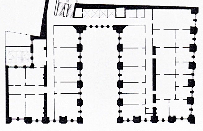
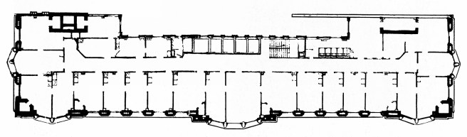
The shallow depth of the Phœnix’s site, a mere 46’ resulted in, once the depth of the single-loaded corridor office lightwell was subtracted, only a ten-foot depth for the lightwell. This apparently posed a subtle challenge to Root in where to locate in plan the elevators and the building’s main stairway. His, by then trademark projected oriel bay into a lightwell, in which he housed the central stair, was not repeated in the Phœnix Building. Was it just too tight to try to push the oriel into the 10′ shallow space, or that an unsatisfactory daylighting performance would result from the over-stuffed lightwell as in the Insurance Exchange?
Nonetheless, when confronted with where to put the elevators, and still be able to use the lightwell as a location for windows to allow the daylight to actually penetrate into the interior of the building and elevators, Root responded with a unique design. He lined the elevators up against the lightwell’s long wall and put lightwell windows directly in back of the elevators, thereby allowing the daylight from the lightwell to penetrate through the elevator shafts and flood the interior corridor of each floor. The shallow depth of the lightwell obviously did not require a skylighted atrium at the ground floor, but as one ascended in an elevator up through the alternating layers of masonry and views to the outside through the glass, who needed the choreographed sequence of an atrium?
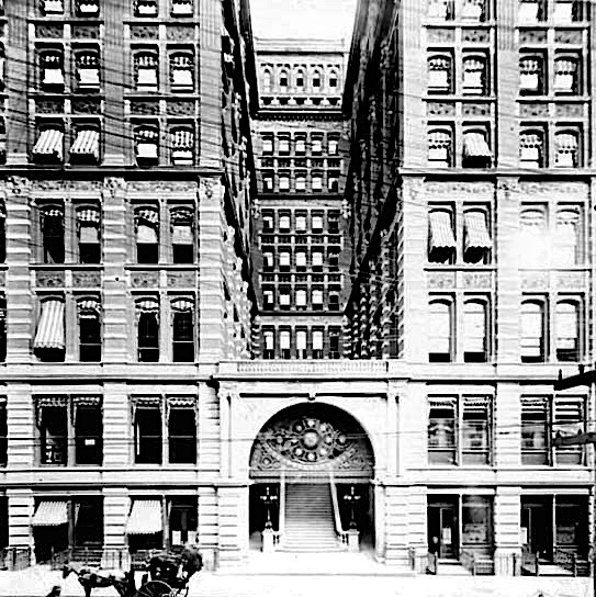
Burnham & Root, Phœnix Building. Lobby. Note the windows in the rear wall, in back of the elevators, that open into the lightwell. These were made possible by Root’s first use of the iron frame in an exterior wall. (Hoffmann, Root)
This decision tasked his engineering intuition to solve a delicate problem: the wall that he had just opened up to the maximum with windows, would also have to support the dynamic loads of the elevators moving up and down. He solved the problem with employing the iron skeleton frame for the first time in a complete exterior wall in Chicago since the 1871 fire. Earlier in the year, Cobb and Frost had used iron columns and beams in the first two floors of the Opera House, and Jenney had placed iron sections within the masonry piers in the upper floors of the Home Insurance Building, but no one had yet to construct a portion of an entire exterior wall from the foundation to the roof using only an iron frame. Root would be the first to do so, and in doing so, would change the history of construction and architectural design.
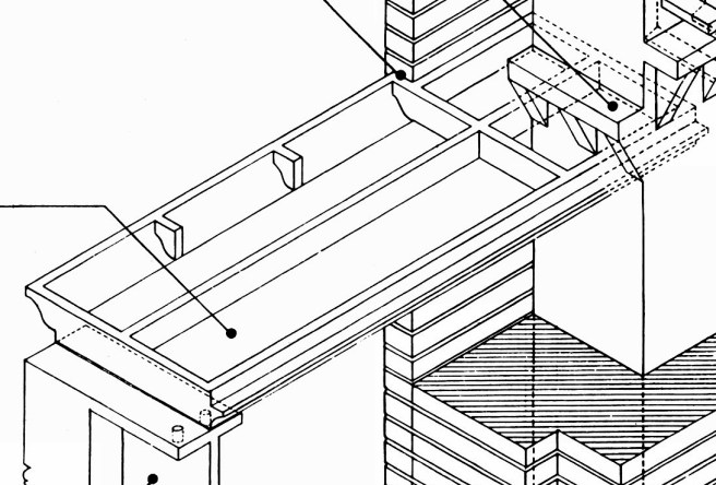
Burnham & Root, Rookery. Structural detail of the light court curtain walls. Note the bearing shelf and web bracket cast with the column. (Thanks to Kevin Wilson at TGRWA, Nathaniel Parks at the Art Institute of Chicago, and Gunny Harboe for helping me to find this image!)
The columns were cast iron that were made with two projecting bearing shelf/web brackets (similar to how the Rookery was detailed as shown): one on the exterior face to support a line of I-beam spandrels, and a similar one on the interior face to support a second line of I-beams. The exterior beams supported a kneewall of 41/2” thick white enameled bricks at each floor, and the interior beams supported a kneewall of 4″ hollow tiles at each floor. The two layers of masonry were probably tied together at the window frame. The existing photographs show that the exterior brick kneewall was continued vertically in front of each column. As this elevation was merely the “back” of the building, little effort went into its design: it was detailed as a brick wall with square openings in it. I will jump ahead a year or so and compare its design to how Root detailed the same situation in the Rookery. In the Phœnix, Root had detailed a continuous band of trim at the heads of the windows at each floor. One could assume that he had wanted to express the iron construction that held the masonry at each floor. Whether this was his intension or not, he did consciously design the Rookery’s lightcourt walls, as they would be visible to the building’s occupants, to express its construction: he added a sillcourse that interrupted the column covering from the spandrel panel, denoting that the masonry spandrel was the dominant feature that was continuously supported not on the columns, but at each floor.
Left- Phœnix Building; Right- The Rookery.
Left: Post, Produce Exchange, 1881. Post had placed the curtain wall within the frame, therefore the columns would naturally be visible; Right: Root chose to emphasize the horizontal to show that the curtain wall was hung in front of, rather than in between the columns.
Left: Ellis, 16 Cook St., Liverpool, 1866. Ellis not only expressed the curtain wall being hung in front of the columns, but also reinforced this detail by keeping the column covering to minimum. This was 60 years before Le Corbusier defined this technique as “the free facade.”
Now let’s return to Jenney and the Home Insurance Building. Its plan shows the same arrangement of elevators and iron framing. I have searched for a photograph or an elevation of the building’s east (rear) façade to no avail. Fortunately, the Art Institute of Chicago has a good set of original drawings from which we can deduce the construction of this wall.
Jenney, Home Insurance Building. Eighth floor plan. (Tallmadge, Field Report)
Jenney, Home Insurance Building. View of SE corner. The nature of the light court walls is unclear. This shows the two-story addition. (Rand McNally view #5)
The only image I have located is this Rand-McNally view in which the nature of the light court walls is unfortunately hidden. I was lucky enough to find one of the floor plans that showed the actual cross-section of the piers in this façade. This dovetails perfectly with a drawing of this detail contained in the 1931 Field Report.
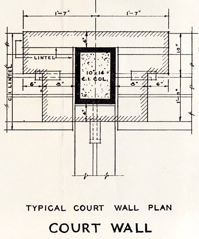
Jenney, Home Insurance Building. Above: Section of the piers in the lightcourt (elevator core). Note that this drawing shows that the piers and spandrels had the same detailing as the exterior piers, i.e., cast iron lintel panels supporting the spandrel’s masonry. The only difference is that the masonry covering the iron section is only 4” thick because it is not subject to the building code because it is not in the exterior perimeter of the building. (Tallmadge, Field Report); Below: Plan of elevator core. Note the plan shows this exact cross-section in each of the piers. (Art Institute of Chicago)
The detail in the Field Report clearly identifies the exact same type of cast iron spandrel pan that Jenney had specified for the street fronts. Even the cast iron column is the same, including its being filled with concrete. The sole difference in the light court piers is the masonry covering is only 4” thick front and back versus in the street fronts it increased in thickness per the building code. The light court was not at the building’s lotline and, therefore, was not subject to this code requirement.
Jenney, Home Insurance Building. Section through the lightcourt wall of the later addition. The section of the spandrel is at the far right. (Art Institute of Chicago)
I was also able to find in the Art Institute’s collection a wall section of the later addition of two floors, in which was shown the section of the spandrels in the light court. This mirrors the exterior spandrel at the far left, meaning that the elevation of the elevator wall was very similar to the exterior elevations. Because the construction of the elevator wall, as I have just laid out, used the exact same structural detailing, we cannot make a claim, for the same reason I rule out the claim for the exterior, that the elevator wall was a true iron skeleton frame. The final nail in the coffin of the legend of the Home Insurance Building for me, after studying it for the past 35+ years is this: no where in the Field Report is there any mention of spandrel beams in the framing of the light court. While the supporters of the Home Insurance Building claim that the intermittent transfer beams in the two street fronts could have been conceived by Jenney as spandrel beams, the fact that there are no such beams in the light court reveals that Jenney had not conceived of his iron framing as a frame. Case closed?!
For what it’s worth, the above discussion leads me to conclude that John Wellborn Root was, indeed, the inventor of the Chicago iron skeleton frame in the elevator wall of the Phœnix Building, recognizing, once again, that his “mentor,” George Post had been the first to use iron skeleton framing in a skyscraper. So can we all try to put the urban legend of Jenney and the Home Insurance Building to rest, once and for all? Please! It was in New York, and not Chicago where the iron skeleton frame and the skyscraper were invented.
Statue of Liberty under construction in Paris, 1883, Génie Civil, 1883. First image of the structure of the Statue of Liberty reprinted in the American Press, American Architect, September 1883. (Loyrette, Eiffel)
What I will document in the coming sections is the process of Chicago’s architects slowly and carefully replacing parts of exterior masonry walls with iron framing, one wall at a time, one building at a time, so as not to weaken the lateral rigidity of the building, until a building could be erected solely with iron framing. While Chicago’s architects were madly rushing in the spring of 1885 to complete these new buildings in time for the start of the new rental year, May 1, the French were exporting Gustave Eiffel’s example of just such a system of advanced iron technology in 214 wooden crates aboard the French frigate Isère directly to New York. Eiffel’s structure arrived in the U.S. on June 17, 1885, but its erection had to wait until the pedestal, designed by Richard Morris Hunt was completed almost a year later.
FURTHER READING:
Gray, Lee E. From Ascending Rooms to Express Elevators:A History of the Passenger Elevator in the 19th Century. Mobile, AL: Elevator World, 2002.
Hoffmann, Donald. The Architecture of John Wellborn Root. Baltimore: Johns Hopkins University Press, 1973.
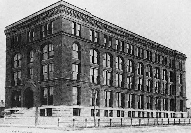
Burnham & Root, McCormick Harvesting Machine Company Offices and Warehouse, Chicago, SW corner of Jackson and Market (Wacker), 1884. (Hoffmann, Root)
I stated that in 1884 Root was still uncomfortable with the vertical scale of a skyscraper’s elevation, a sentiment shared by many historians who have critiqued the Phoenix Building. On the other hand, given a shorter building, Root could show his growing command with the horizontal. Such was the case with a building for the estate of the late Cyrus H. McCormick that Burnham & Root were hired In September 1884 to design for the southwest corner of Jackson and Market (Wacker) Streets, especially when it is compared with his earlier effort with such a program in the Santa Fe Building in Topeka.
Burnham & Root, Atcheson, Topeka, and Santa Fe Building, Topeka, Kansas, 1883. (Hoffmann, Root)
Burnham & Root, McCormick Harvesting Machine Company Offices and Warehouse, Original Seven Story Design. (Hoffmann, Meanings)
Originally designed with seven floors, Root had layered the elevation in a 1:2:3:1 sequence. Before construction began in December 1884, the owners had eliminated a floor, allowing Root to revise the building’s elevation into a tripartite scheme of base, four-story arcade, and top. Because of the similarities in massing, there can be no doubt that Root used Peabody & Stearns’ R. H. White warehouse as a model for the McCormick Building.
Peabody and Stearns, R.H. White Warehouse Store, Boston, 1882. (American Architect, September 15, 1883)
Root employed the “boxed” construction of the masonry wall and detailed its five-storied arcade into a perfect expression of masonry skeletal construction. Like the Insurance Exchange, the McCormick Building’s arcade extended for four stories, but his understated horizontal between the base and the upper body in the McCormick Building still allowed the piers to be read as extending to the foundation rather than sitting on the base, imparting a truly skeletal nature to the elevation. Also, as he had detailed in the Insurance Exchange, Root had “ghosted,” or silhouetted the arches with alternating bands of masonry. Whereas in the Insurance Exchange he had raked the horizontal joints in the brickwork to create the horizontal banding, in the McCormick Building it appears that he employed a darker material (brick, terra cotta, or stone) to create the dark lines that were separated with lines of the same brick used in the rest of the building’s body. I would assume that he wanted the same effect as what he had achieved in the Insurance Exchange, but because the McCormick’s arches were at least twice as large, he needed these horizontals to have a larger “read” than what could be gained with a single course of brick.
Root’s only significant departure in the design of the McCormick Building from its Boston precedent was his first experiment with the triple window, that was most likely inspired by Flanders’ Mallers Building, Chicago’s tallest office building. The visual appropriateness of detailing a triple window, rather than a double, under an arch is easily understood when one looks at this building. As opposed to all of the other arches in the McCormick’s exterior, Root used a double window under the arch in the entrance bay. Here, the center mullion is allowed to extend to the underside of the arch at its midspan, resulting in a visual support of the arch directly where an arch is supposed to be spanning. Hence, the arch’s structural integrity was completed eviscerated.
FURTHER READING:
Hoffmann, Donald. The Architecture of John Wellborn Root. Baltimore: Johns Hopkins University Press, 1973.
As construction of the Mallers Building paralleled that of the Insurance Exchange just across the street, it is inconceivable that Root did not take note of Flanders’ detailing. In June 1884, Burnham & Root were commissioned by a stock company headed by another of John Sherman Stockyard’s clients, Archibald McNeill, co-owner of the meatpacking company Libby, McNeill, and Libby, to design an office building on the block bounded by Jackson, Clark, and Pacific Streets.
Burnham & Root, Phœnix Building, Chicago, SW corner of Jackson and Clark, 1884. (Hoffmann, Meanings)
This was a prime location as it was directly east of the Board of Trade, faced the Grand Pacific Hotel, and was diagonally across from the Post Office. In a sense, it was the link or pivot between Chicago’s two prime areas of development at this time: the Post Office Square and the Board of Trade district.
Map of the Board of Trade (H) area: La Salle and Clark Streets are shown. (Author’s collection)
The owners were able to entice the Phœnix Insurance Company of Brooklyn to be the major tenant of the building, hence it was named the Phœnix Building. Although a building permit was obtained in October 1884, construction was postponed, as was the case with the Rialto, until late in 1885. Nonetheless, Root’s design of the Phœnix Building can be viewed as a direct evolution of the Rialto and the Insurance Exchange with the addition of bay windows inspired from Flander’s Maller Building.
Like the Rialto and the Insurance Exchange, Root was once again faced with designing a thin slab office building. In his essay, “The Value of Type in Art” published in Inland Architect in November 1883, Root had identified the value of typology in design:
“Now this adherence to type is one of the best tests of every good work of art, and forms one of the most infallible bases of criticism. Of every good work of art it is true that the first thing necessary is to put before one’s self the conditions of the problem to be solved, and then trace the consistency of the various solutions followed by the artist.”
And so we sill do just that. While the Jackson Street front was the longest elevation he had yet designed (216′ vs. the Burlington’s 199′), the site was only 46′ deep. The depth of the lot only permitted lining the three street faces with single-loaded offices in an elongated U-plan with a shallow lightwell in the rear (less than 10′ in depth) that allowed the addition of four more offices per floor.
Following the relatively successful horizontal composition of the Insurance Exchange’s elevation, Root experimented (I view this as more of an improvisation than a composition) with the design of the Phœnix. This may have been due what I perceive is a lack of a “theme” or inspirational spark. (As opposed to Rialto, where Root was inspired by the bridge between the Board of Trade and his building to conceive of the Rialto as a play on Venice.) First, he arbitrarily reversed the order of the Insurance Exchange’s layering of its middle floors from base / two-story colonnade / “belt” story / four-story arcade / one-story cap into the Phœnix’s base / one-story transition / three-story arcade / “belt” story / two-story colonnade / one-story cap. This resulted in a seemingly meaningless position of the now gratuitous arcade. He also continued experimenting with the joint between the stone base and brick body that he had initiated with the Insurance Exchange. This time he inserted a transitional story between the two-story stone base and the upper body of brick, that read as an overlap of the two languages. This he accomplished by alternating layers of the base’s stone and brick of the upper body, channeling the design of his “mentor” George Post in the Mills Building.
George B. Post, Mills Building, New York, 1881. (Landau, Post)
As Root had detailed the top floor of the Rialto, he once again employed a unique rectangular language to demark the top floor in the Phœnix, that echoed Post’s elevation of the Produce Exchange’s interior light court. This was a starkly utilitarian elevation, that hinted at the rational ‘Chicago School” elevations to come. In summary, whereas Root had toyed with giving the Insurance Exchange a vertical accent capped with the arcade in its upper body that was reinforced with the extruded corner turrets, it was if he had immediately rejected this verticality in the Phœnix and returned to the traditional horizontality of architecture. The repetitive elevation of the Phœnix’s top floor reinforced by its emphatic balcony (and the understated corner “buds” vs. the Insurance Exchange’s turrets) relayed Root’s uncomfortableness in 1884 with making a skyscraper with a vertical accent. (I am arguing with myself on this point because I cannot ignore the fact that the 216′ length of the facade would make it extremely difficult to pull off a vertical accent, but Root had just done so with the Rialto. My point is that Root at the “midpoint of his career” in 1885, was still hesitant to take the leap in changing the paradigm of the skyscraper to express its growing dominant dimension.)
Left: George Post, New York Produce Exchange, Elevation of the interior light court; Right: Phœnix Building. Root, as had Post, set a regular grid of openings of which the one with the structural member located behind it is blank. Root has inverted the positions of the rectangular and the square windows. Note that Root has shrunk the corner turrets.
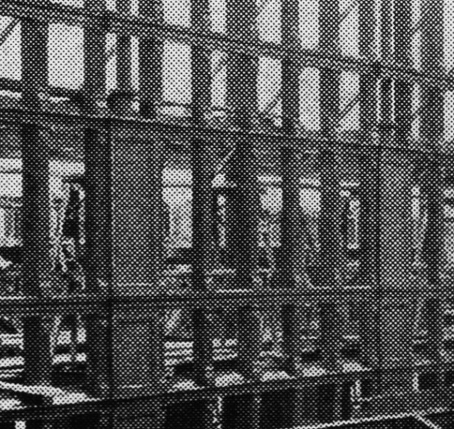
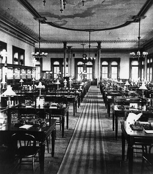
The top floor in the Phœnix Building was appropriately occupied by the insurance company that Root expressed with a continuous balcony, obviously taken from the Rialto (and Post’s Western Union Building), that allowed the company’s employees to go outside and enjoy the view. Root designed the “workroom” as one continuous double height (22′ high), 216′ long space, similar to how Post had designed the top floor in the Western Union Building, some eleven years earlier (this concept is now commonly referred to as the “open plan”). The long dimension of the space opened to the north, perfect for daylighting. The two storied space allowed Root to easily locate a second floor/mezzanine for the managers, again refraining Post, albeit this time the mezzanine that Post had employed in the Banking Hall of the Equitable Building.
George B. Post, Western Union Telegraph Building, New York, 1872. Top floor, operations room. (Online)
Burnham & Root, Phœnix Building. Top floor. Another early example of the universal space or “open office concept.” (Hoffmann, Root)
Post, Equitable Building. Banking Hall. (Landau and Condit, New York)
While Flanders had experimented with bay windows to gain additional square footage in the Maller Building because of its tight site, one cannot say the same thing about the Phœnix’s site. If the lack of space was an issue, surely Root would have included many more bay windows than the gratuitous few he employed. These were simply a formal experiment on the part of Root, once again pointing to improvisation. Similar to the design of the Burlington’s elevations, he used the bay windows in an inverted relationship between the facades.
Left: Phœnix Building. (Chicagology.com); Right: Burlington Building.(Hoffmann, Root). Examples of Root inverting his elevational motif between two intersecting facades.
In the long Jackson elevation, a semicircular, two-windowed bay window was located at both ends to form Root’s characteristic corner pavilions or bookends. The location of the same device was then inverted on the two short ends to be in the center that was, in turn, bookended by heavier corner piers. The largest of the bay windows, a three-windowed faceted bay was located in the middle of the Jackson facade, to emphasize the central position of the entrance. Root reinforced the center of the composition, as he typically had done in earlier designs, by slightly projecting the entire central bay of the facade beyond the surface plane of the rest of the elevation.
Left: Rialto Building; Right: Insurance Exchange. Note the entry entablature is rising from its second-story location in the Rialto to its fourth-story location. Root will elevate it to the cornice in the Phœnix Building.
As one compares the Rialto, the Insurance Exchange, and the Phœnix as a progression, the entry entablature over the main entry is seen to be moving up the front of the building, until it breaks past the roofline in the Phœnix. In the Phœnix, Root seems to have used the central bay window as a link between the grand, arched portal at grade and the curved pediment at the roof.
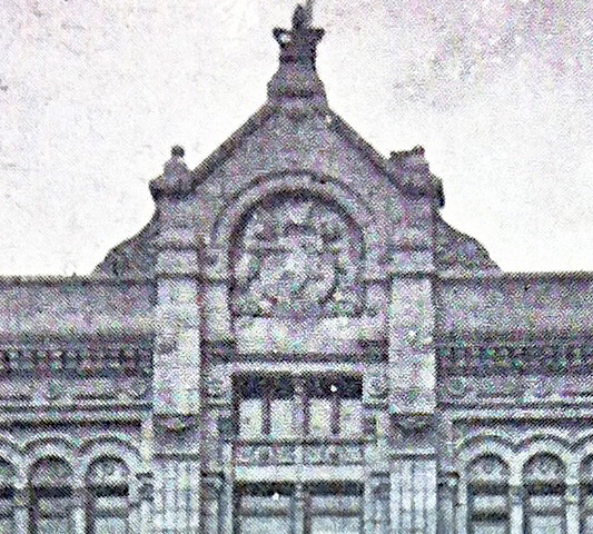
Correspondingly, he reduced the dimensions of the roof’s corner turrets so that they would not compete with the central pediment. The location of what Donald Hoffmann has described as the “yoke-like” pediment can also be viewed as Root’s response to Boyington’s Jackson Street elevation of the Royal Insurance Building, located a mere block away on the opposite side of Jackson Street. As Boyington had placed the coat-of-arms of the Royal Insurance Company in the central pediment of its building, so had Root located a terra cotta panel of a phoenix in his pediment. If one is looking for a “theme” that Root had used for this building, the only one I can identify is here, at the apex of the cornice, where the Phoenix has arisen in its full glory.
Map of La Salle and Adams near the Board of Trade (H). (Author’s collection)
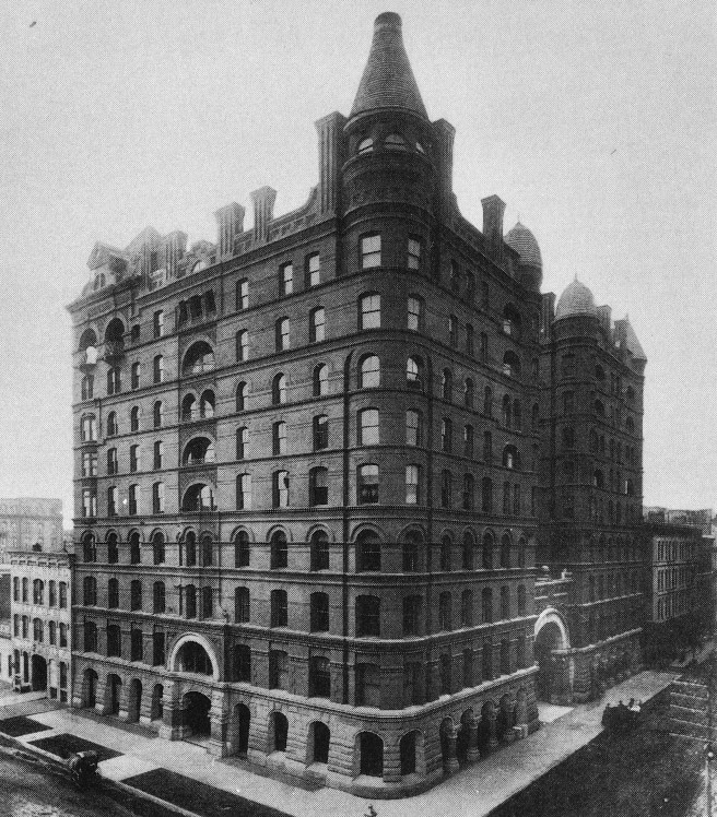
In the second week of March 1884, Marshall Field obtained a permit to build a 13-story office building on the southwest corner of La Salle and Monroe Streets, diagonally across the block of La Salle Street from the site of the 10-story Home Insurance Building. For this structure, Field departed from his preference in the design his Prairie Avenue residence for hiring out-of-town architects (Richard M. Hunt). Field logically hired S. S. Beman, the architect that his card partner George Pullman used to design his own downtown office building. Field wanted to do his friend one better, so the Field Building was designed with 13 floors to top off at 170,’ five feet taller than Pullman’s. Most likely influenced by Boyington’s successful use of all-granite facades in the Board of Trade and the Jackson Street elevation of the Royal Insurance Building, Field had Beman design the office building not in the currently fashionable brick, but completely in traditional rock-faced and polished granite.
Knowingly or not, in designing the Marshall Field Building, Beman had become involved in the vicious spite battle between two of Chicago’s merchant titans, Field and his former partner, Levi Leiter. I last mentioned these two partners in the rebuilding of the Singer Building, the home of Field & Leiter, that had been destroyed by fire in Nov. 1877. (see Sec. 3.11) The partners had agreed between themselves to buy the new building and lot for $500,000. But Singer demanded $700,000 and during the final negotiations while Field was in New York, Leiter, according to their plan, rejected the offer. Instead of lowering its price, Singer turned to their competitor, Carson, Pirie, Scott and offered them an annual lease for $70,000. Not wanting to lose the iconic corner on State Street, the two partners had ponied up the $700,000 from their personal funds, in addition to an extra $100,000 to compensate CPS to break the lease. Field’s biographers record that Field blamed Leiter for this debacle, but this was, by no means, the only reason for Field wanting to be rid of his partner and friend for the past sixteen years. Robert Twyman laid out a compelling case where Field not only wanted to be in sole control, but also wanted to reward his next generation of managers with partnerships, and this could only happen if Leiter’s percentage was available to offer these new partners. Field and Leiter’s partnership contract was up for renewal on January 31, 1881. Field, using their existing contract, mounted a well-orchestrated campaign that forced Leiter to sell his stake in their company to him, and their partnership was had been dissolved on Jan. 26, 1881.
Apparently, the break-up settlement had divided the holdings of the company between the two partners, as Leiter was given ownership of the adjacent lot to the west of Field’s corner site. Leiter had immediately proceeded to erect a five-story building on his site, locating, as was convention but without any prior arrangement, the east party wall midway along the property line, half of the wall’s thickness on his lot, half on the corner lot. Field eventually had acquired the corner lot for his new office building and struck an agreement with his former partner to use the mutually-owned party wall to support the new office tower. Field promised to increase the wall’s strength and foundation to support the loads of the new building, as was typical of the era, without injuring Leiter’s existing building on the west side of the wall. Excavation for the new Field Building proceeded through the summer of 1884, with the foundation being completed by September. Construction then came to the traditional halt with the onset of winter.
The postponement may also have been a tactic on Field’s part to publicly leverage Leiter, because at this time there was no technique to increase the strength of the existing wall and its foundation without getting under Leiter’s existing building. Leiter, rather cleverly I might add, had interpreted their agreement as stating that all of the construction needed for Field to use the party wall would be done on Field’s side of the wall (that, of course, at this time was impossible). Leiter simply had legally outsmarted his ex-partner, and further allowed Field to dig himself literally into a deeper hole. In March 1885, Field ordered Beman to complete the details of the building and construction on the site was renewed. Field approved breaking into Leiter’s basement in order to shore up the existing wall and to place the new foundation. Leiter countered by obtaining a permanent injunction in May 1885 against Field from doing any more construction on Leiter’s side of the wall. Field was eventually vindicated the following year (in May 1886) when the Illinois’ Supreme Court ruled that the original agreement was a party wall contract, implying that the easement of support was given to both parties, and that one party could not have the benefits without submitting his property to the requirements of support for either party. However, while Field had won the battle, he lost the war, for the time lost during the postponement in construction would kill the project as the building boom had oversaturated the rental market. Somewhat ironically, although the height limit ordinance had failed to be approved by council, the tallest of the skyscrapers (13 floors) planned for the Board of Trade district was not allowed to grow out of Chicago’s soil. The open excavation pit remained a scar exposed for five years on one of Chicago’s most expensive pieces of real estate: a grim testament to the realities of building tall structures on Chicago’s soil, as well as to the ferocity of the real estate battles being waged at this time on Chicago’s soil by America’s merchant princes. (By the way, the battle between these two giants had only just begun…)
FURTHER READING:
Twyman, Robert W. History of Marshall Field & Co. 1852-1906. Philadelphia: University of Pennsylvania Press, 1954.
I’d like to thank Brian Kelly of “brianbrands.com” for offering his knowledge of the Field/Leiter relationship.
John J. Flanders, Mallers Building, Chicago, 1884. On the left is the Gaff Building and on the right is the Quincy elevation of the Royal Insurance Building. For perspective, note the pre-skyscraper buildings at the far right. (Van Zanten, Sullivan’s City)
The next building for which a building permit had been granted in March 1884, once again to avoid the pending height limit, was to J. B. Mallers for Chicago’s first 12-story office building that would top-off at 175.’ The site chosen was the last buildable front on La Salle Street in the block immediately north of the Board of Trade. This was at the southwest corner of La Salle and Quincy, a tiny plot with a 38′ frontage along La Salle and a 60′ exposure on Quincy, across the street from the Insurance Exchange. The corner was bookended by the Royal Insurance Building on the west and the Gaff Building to the south.
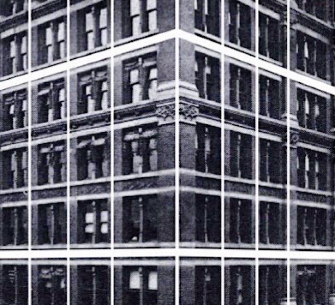
The west side of La Salle Street. From the Board of Trade: Counselman Building, Burnham & Root; Gaff Building, Stephen V. Shipman; Mallers Building; Insurance Exchange, Burnham & Root. (Chicagology.com)
Such tight conditions provided quite a challenge to John J. Flanders, the architect chosen by Mallers to design the building. Most likely utilizing a party wall contract, Flanders used the two existing party walls for support. Along the two street fronts he placed large masonry piers to support the floor girders of the interior iron frame. He chose to emphasize the corner pier not only by increasing its size to accommodate each floor’s safety vaults, but also by giving it a rounded profile. In order to gain as much rentable floor area as possible, Flanders not only pushed the glazing out as far as possible to be flush with the exterior face of the masonry piers, but also cantilevered a bay window that extended continuously for eight stories in floors 2-9 on each street front. These were supported by an iron framework connected to the masonry piers and clad with terra cotta.
Flanders arranged the elevation into four layers in with a decreasing rhythm of 4:3:2:3 that increased the building’s sense of height through its play with perspective. I think the four-story base was very ingenious in how he had interlocked the stone base with the brick/terra cotta body by carrying the terra cotta spandrels into the base, a much more integrated solution than the typical solution of simply placing the brick body on a stone base, that also reinforced the vertical nature of the elevation. He then capped the tower with a three-story arcade plus projected cornice that created, for all practical purposes, an eleven-story arcade. He had taken Labrouste’s Bibliothèque Sainte-Geneviève and extruded its elevation to the requisite 175.’
The influence of Boyington’s Royal Insurance Building is evident in the triple windows from the Jackson elevation (with the exception that Flanders did not use the “Chicago window” spacing) and the layered articulation and arcaded top of the adjacent Quincy elevation.
W.W. Boyington, Royal Insurance Building, Chicago, 1883. Jackson Street elevation. (Gilbert, Chicago )
Meanwhile, the bay window may have been a first for a Chicago office building, but the device, that had been used in hotels for some years, most notably being the Palace Hotel in San Francisco had already been used in Chicago by Burnham & Root in the Brunswick Hotel, located across Adams Street from the Pullman Building.
Left: John P. Gaynor, Palace Hotel, San Francisco, 1871. (Online); Right: Burnham and Root, Brunswick Hotel, Chicago, 1883. (Hoffmann, Meanings)
Flanders’ use of flush-glazed triple windows and continuous bay windows elicited the attention of the Inland Architect that described them as a “unique feature and a thorough novelty” that would “excite much curiosity and comment because of its peculiar style.” Truly, Flanders had begun to integrate in the Mallers Building some of the iconic details that were emerging in the design of Chicago’s tall office buildings.
Flanders, Mallers Building. Compare the flush windows with those on the left that are stepped in and how this detailing makes the wall look more like a surface than a mass of brick.
Jenney, Home Insurance Building. Surviving fragment of the iron structure in the Museum of Science and Industry. Note the stub spandrel beam (at the left of the column) that the Field Committee chose to include in the fragment left for history. As this beam was located in only three of the eight floors that were skeleton-framed, the committee attempted to mislead future historians about the true nature of Jenney’s structure, (Author’s collection)
I have now shown you a litany of tall buildings in which some aspect of iron skeleton framing had been incorporated in their exteriors before Jenney first experimented with it in April 1884 for the Home Insurance Building. (There is no issue about interior iron skeleton framing in 1884, it was ubiquitous by then.) The independent iron frame with a masonry curtain wall had been in service in the U.S. for some twenty-five years following Bogardus’ New York shot tower of 1855. As far as I have been able to determine, George Post in New York had been the first American to use iron framing in an exterior wall since the urban conflagrations of Chicago and Boston in his detailing of the exterior lightcourts in the New York Produce Exchange (1880), and the Mills Building (1881), and just maybe even before the fires in in the Equitable Building (1867). These experiments were soon followed in Chicago by Root in his lightcourts for the Insurance Exchange, Phoenix Building, and also, of course, The Rookery (see an upcoming post).
George Post, New York Produce Exchange. Left: Photo of Construction showing the iron skeleton framing in the lightcourt walls. (Landau and Condit, New York) Right: Elevation and section of the lightcourt’s exterior walls. (Landau, Post)
So are we then looking for the first building whose exterior structure was solely iron framed? If so, that leaves the Home Insurance Building out of the running because it still had two exterior loadbearing masonry party walls, in addition to the first two stories of its streetfronts having been solid masonry. It will be a cautious step-by-step process in replacing the tried-and-true (and very stiff with regards to wind loads) bearing wall in the exterior of building with the iron frame. The first all iron-framed tall building will be erected in 1888, and we’ll try to ascertain which building and architect/engineer deserves to be so credited when we get to that year.
Jenney, Home Insurance Building. Eighth floor plan. (Tallmadge, The Origin of the Skyscraper)
Admitting that the Home Insurance Building was neither the first skyscraper nor the first building completely framed in iron, then what “first-in-the-world” title is left for it to claim? (And why bother, other than for some civic boosterism on the part of Chicago?) I think the best that one might argue is that it was the first use of iron skeleton framing in the exterior of a tall building in Chicago? (Remember, Post had already accomplished this in New York.) Let’s examine this claim: that is, Jenney had used iron skeleton framing in the upper eight floors in the two street fronts.
Jenney, Home Insurance Building. Reconstruction of the structural detailing of the exterior piers. (Drawing by Deborah Cohen Heller and Maxwell Merriman)
From the evidence on record, we can conclude (please refer to my 1987 JSAH article for a more detailed explanation) from at least eight points that Jenney’s loosely-bolted, eight-story framework of masonry-stiffened cast iron columns and lintel pans was not entirely self-sufficient and independent of the masonry, and, therefore, does not qualify to even be called iron skeleton framing:
Jenney, Home Insurance Building. The exterior iron structure overlayed the building’s elevations, showing the lack of spandrel beams in Floors 5, 7, 8, and 10. (David Burwinkel)
-First, there were no spandrel beams at floors 5, 7, 8, and 10. By definition, a frame is a rigid assembly of columns and beams at each floor (unless one is speaking about a megaframe, that in 1884 was in the distant future…);
Jenney, Home Insurance Building. Section and elevation of structural iron members in the exterior, showing the location of the transfer beams at
Floors 4, 6, 9, and roof. It is more important, however, to understand that there were no spandrel beams in Floors 5, 7, 8, and 10. (Jensen & Halstead, Ltd., Chicago)
–Second, he did not initially refer to the masonry as a covering, but always stated that he had embedded the iron column within the masonry pier in order to reduce the size of the piers and, thereby, maximize the amount of daylight entering the interior;
Jenney, Demolition of the Home Insurance Building, 1931. (Tallmadge, The Origin of the Skyscraper)
–Third, unlike a skeleton frame, Jenney had filled his iron columns with concrete, which is completely unnecessary in a skeletal-framed building (with the exception of contemporary composite structures);
-Fourth, the lintel pans were not one continuous piece of iron that spanned from column to column (therefore, they were not a “beam”) but comprised of two pieces, not mechanically connected, that spanned only from a column shelf to the intermediate mullion, thereby offering no rigidity to the structural bay whatsoever;
– Fifth, the lintel pans were also not bolted to the columns, so rigidity of the mullion/lintel assembly was gained through the masonry in the spandrel wall;
-Sixth, the exterior brick facing of the piers, whose thickness increased to 12 inches at the corner and entrance piers, was not supported on the iron column at any point, thus it was continuously bearing for eight stories from the granite piers. (remember that Jenney had notched the pans so that the facebrick could run continuous without any connection to the spandrels in an attempt to minimize cracking in the facebrick should the spandrel rotate caused by differential settlement). In fact, Jenney had gone so far as to specify a very conservative technique of bricklaying for the piers’ face brick to achieve a stronger-than-usual assembly to keep the cross section of the masonry piers to a minimum. Selected hard brick was used with a strong cement, not lime, mortar and was laid up in very tight, solidly packed joints. This would have been entirely unnecessary if Jenney was supporting the face brick on the iron frame at each floor. The importance of this point is that the concept of the iron frame is to completely support its masonry enclosure, which it definitely did not do in this building;
-Seventh, as the columns typically extended laterally unbraced by iron beams for two stories (the spacing of the transfer beams that supported the mullions), and in the middle of the building for three stories, the columns more typically relied solely on the rigidity of the spandrel masonry interacting with the masonry pier to stabilize the connection against lateral loads and to brace the columns at each floor against buckling;
-Eighth, and finally, the iron frame with its loosely bolted and clamped connections could not have resisted any wind loads.
What I have tried to show is that Jenney’s detailing was consistent with what he had originally claimed was his objective: he had embedded the iron column within the masonry pier that then allowed him to reduce the size of the masonry piers’ cross-sections. Jenney’s structure in the Home Insurance Building did not generate much contemporary attention or acclaim in the U.S., or for that matter, even in Chicago, during its construction nor immediately following its completion. Was there any reason for such construction to have done so? Most likely it was viewed by Chicago’s architects and builders as an eccentric curiosity because I am not aware of any Chicago architect that employed Jenney’s details in any building in Chicago. The Home Insurance Building was simply just one of a handful of skyscrapers that were under construction in Chicago during 1884.
Solon Spenser Beman, Pullman Palace Car Building, Chicago, SW corner of Michigan and Adams, 1883. (J.W. Taylor: Chicago Historical Society)
Even during its construction during the latter half of 1884, Jenney himself modestly spoke of S.S. Beman’s Pullman Building as the highpoint of Chicago’s architecture. In fact, as the Home’s iron columns began to be erected in August 1884, Inland Architect stated that the commission for the Union League Club, and not the Home Insurance Building was “the greatest compliment Mr. Jenney has yet received professionally.” Union League Clubs had initially sprung up in the North during the Civil War and had naturally subsided once the war had been won, but by 1880 it was evident to these men who had defended their country earlier, that the country was once again inching ever closer to civil war, but this time the enemy was Socialism. So Union League Clubs were reestablished nationwide in 1880 purposefully “to encourage and promote by moral, social, and political influence, unconditional loyalty to the Federal Government, and to defend and protect the integrity and perpetuity of this Nation.”
William Le Baron Jenney, Union League Club, Chicago, SW corner of Jackson and Custom House Place, 1884.
(Chicagology.com)
If Jenney’s use of iron in the Home Insurance Building had been considered to have been of a revolutionary nature, surely it would have been quoted in any of the obituaries for Daniel Badger who died in November 1884 and was referred to as “the first person in this country to use iron on a large scale for building purposes.” Not surprisingly, following Jenney’s description of its structural system at the 1885 A.I.A. convention in October, the Home Insurance Building and the potential of its “unique” structural system were not discussed for the next two and a half years in local or American trade magazines or conference proceedings. In fact, nobody in 1885 had the time to worry about such esoteric points as the construction market in Chicago was still completing the erection of all those buildings that were started in 1884.
And even once this issue had eventually ignited in the construction press, there were still those in Chicago who, not for a moment, gave the legend any creditability. Peter B. Wight, who outlived almost all of those in the Chicago School, was the fireproofing contractor not only for the Home Insurance Building, but also many of the other buildings that would be posited for these honors, later claimed to have introduced Jenney to Normand Patton, Chicago’s leading designer of iron structures, in order to help with the design of the iron elements planned for the Home Insurance Building: “Jenney could talk building better than any man I knew, but he knew very little how to design and construct them and depended on others.” In fact, in 1950 a former Jenney employee, Elmer C. Jensen, who had entered Jenney’s office in March 1885 as an office boy and became a partner in the firm in April 1905, had admitted that he was always puzzled over the fact that “Major Jenney never made any claim that he had originated the skyscraper principle.”
“Frame-construction,” Burnham and Root, Reliance Building, 1890, 1894. (Online)
Therefore, if one adopts the definition of a skyscraper that is a tall building constructed solely with a metal skeleton frame, one needs to ascertain what was the first such tall building erected, for it was not the Home Insurance Building. So when did the Home Insurance Building and its structure become such a contentious issue? There will be an event that will spark the argument, but this won’t occur until 1888. I think the time is overdue for this urban legend to be laid to rest. Therefore, if you hear of anyone still citing the Home Insurance’s reputation, feel free to bring this post to their attention. I will be more than happy to debate anyone at any time about this issue. In fact, I’ve already laid out my opening arguments above.
FURTHER READING:
Larson, Gerald, “Toward a Better Understanding of the Evolution of the Iron Skeleton Frame in Chicago,” Journal of the Society of Architectural Historians, March 1987, pp. 39-48.
Tallmadge, Theodore E. The Origin of the Skyscraper-The Report of the Field Committee. Chicago, 1934.
Jenney, Home Insurance Building. Surviving fragment of the iron structure in the Museum of Science and Industry. Note the stub spandrel beam (at the left of the column) that the Field Committee chose to include in the fragment left for history. As this beam was located in only three of the eight floors that were “skeleton-framed,” the committee attempted to mislead future historians about the true nature of Jenney’s structure, (Author’s collection)
It appears that as the building had increased in height from the initial seven floors of February 19, 1884, to the final ten stories of April 28, Jenney became concerned about the size of the masonry piers in relation to the need for daylighting (just as Baumann had likewise identified) and most probably began to experiment during the latter part of this period with embedding iron sections within the masonry piers that would support the floor beams in order to keep the piers’ cross section to a minimum. This concept of embedding iron sections within a masonry structure to augment its capacity was consistent with an article that Jenney had published in the preceding year, in which he revealed his understanding of iron framing just before he had received the Home commission: “Educated architects in Europe… have been working with and writing on the combination of stone, brick and iron, in the street elevations of buildings.” In other words, he did not mention the concept of an iron frame supporting its exterior masonry curtain wall but spoke instead of the structural combination of brick and iron. This combination clearly reflected his French training and familiarity with French theorist Viollet-le-Duc’s ideas about the use of iron and masonry.
Jenney, Home Insurance Building. Eighth floor plan. (Tallmadge, The Origin of the Skyscraper)
The building’s interior structure was the by-then standard iron frame protected with Wight’s terra cotta casings. Also standard were the two masonry bearing party walls on its north and east that ran the entire height of the building and provided much of the building’s lateral stability.
Jenney, Home Insurance Building. View of SE corner. Note the continuous masonry bearing wall along the east lotline. This shows the late addition of two stories. (Rand McNally view #5)
In fact, even the first two stories of the street fronts also were loadbearing rock-faced granite piers, battered in thickness from 4′-0″ at the base to 2′-10″ at the third floor. Constrained by the building code’s requirement for masonry exteriors, the only detail in which Jenney had departed from standard Chicago construction of the early 1880s was his insertion of a rectangular, concrete-filled cast iron section within the exterior masonry piers in only the upper eight stories of the two street fronts. In a sense, Jenney had inverted the structure of the Opera House Block, except that Cobb & Frost had also included spandrel beams (see below) and used the exterior iron columns in the first two floors to support all, and not just a portion, of the weight of the floors above.
Jenney, Home Insurance Building. Reconstruction of the structural detailing of the exterior piers. (Drawing by Deborah Cohen Heller and Maxwell Merriman)
The iron sections were story-high, hollow cast-iron sections that supported the floor beams. These sections were set on the top of the granite piers at the third floor and were bolted one on top of another, helping to support the upper seven floors and roof. These sections were cast with shelf brackets to support two 12-inch deep wrought iron floor beams. These beams were loosely bolted to the column by a single bolt that passed through the beam webs and connected them to a spacing bracket that was also cast with the column. As tolerance was needed for erection, the holes were larger than the bolt, leaving the connection with a considerable amount of play. Therefore, Jenney had incorporated a clamp that was a one-inch diameter wrought iron rod that was bent at one end and placed into a notch cut into the top flange of both beams. The rod on the other end was threaded, allowing it to be connected to the column by a nut placed inside the column, thereby pulling the beams tight to the column face, after which the iron column was filled with concrete. The concrete-filled iron column was then surrounded with masonry that at times exceeded twelve inches in thickness, creating a solid cross section in the building’s exterior piers. In the first article he published on the building in the December 1885 issue of Inland Architect, rather than describing this technique as wrapping or enclosing the iron column with a masonry skin, Jenney stated that he embedded the iron column within the masonry pier: “a square iron column was built into each of the piers in the street fronts.”
Jenney, Demolition of the Home Insurance Building, 1931. (Tallmadge, The Origin of the Skyscraper)
So far, so good, but now Jenney’s structure becomes more “complicated” (I choose my words carefully). Jenney was very concerned about the potential of differential settlement in his first tall building. (This was evident in the title of a paper he delivered at the October 1885 A.I.A. convention, “The Construction of a Heavy Fireproof Building on a Compressible Soil.”) He was not at all reassured by contemporary reports of the foundation problems in all three of Chicago’s new large public buildings, the Post Office, the City Hall (not yet completed!), and the Board of Trade’s tower (still under construction) that surely would have made him overly-cautious in how he would detail the structure to minimize any problems. With these reports fresh in his mind, the last thing that Jenney would have wanted to detail in the Home Insurance Building would have been a rigid framed structure.
Drawings of Cracks in the Board of Trade due to the differential settlement of the Tower. Chicago Tribune, January 21, 1894. (Chicagology.com)
If Jenney had conceived this structure as a skeleton frame, he would have simply placed an iron spandrel beam connected at both ends to the columns that would have supported the window wall above. This Jenney did not do. One can imagine any number of reasons for his decision: my best guess is that a long iron beam at every floor in this location was too expensive, because this was exactly what Jenney did not detail. Instead of spanning this distance with a single iron beam upon which he could then place the masonry spandrel panel and paired windows, he still placed the conventional vertical structural iron mullion between the windows and then used a shallow iron pan to span between the pier and the mullion, i.e., he broke the single span between the piers into two spans, that met at, and were supported by, the intermediate iron mullion. This traditional structure of the paired window and mullion, as we have discussed before, had the inherent problem of differential settlement between the heavily-loaded piers and the lighter mullions because it was still conventional practice, even though Baumann had argued against it, to put the same size footing under both elements. This resulted in the heavier-loaded piers settling at a greater rate than the smaller mullions, transferring more and more load to the mullions, and often resulted in cracking around them. Chicago’s poor soil only seemed to exacerbate this problem, as we saw in Richardson’s American Express Building (see Vol. One).
Left: Foundation problem with intermediate piers. Right: Foundation solution for alternating piers and mullions: to transfer the load in the intermediate mullion to the main piers. (Baumann, Foundations)
Therefore, instead of using iron beams to span between the piers, Jenney detailed cast-iron lintels in the form of four-inch deep hollow pans, also filled with concrete like the columns, that spanned the distance between a column shelf bracket and the intermediate cast-iron mullion. The cast-iron lintel pans were as wide as the masonry spandrel walls that were constructed on top of them. As if the street fronts were still considered to be bearing walls, the spandrels, for no other conceivable reason, increased in thickness along with the piers, as required by the building code, from 20 inches in the top three floors to 24 inches in floors 5-7, to 28 inches in floors 3 and 4.
The lintel pans were not bolted to each other, to the mullion, or to the column brackets, but simply rested on these surfaces, relying solely on the supported masonry knee wall that was bonded into the masonry pier, to hold the armature laterally in place. The lack of bolts may have been a technique on Jenney’s part to impart some rotational flexibility at the column/spandrel connection to accommodate differential settlement of the piers. This flexible joint was augmented by notching the front of the iron lintel four inches back from the face of the pier, which allowed the pier’s exterior face brick to continue past the lintel so that the pier’s face brick would not be supported at any point along the lintel. This detail minimized the potential of the face brick to crack if an iron spandrel rotated due to the settlement of an adjacent pier, but it also meant that the pier’s eight-stories of brick facing was continuously self-supporting from the granite piers at the third floor and was not supported at each floor on the iron column.
Jenney, Home Insurance Building. Section and elevation of structural iron members in the exterior, showing the location of the transfer beams at
Floors 4, 6, 9, and roof. It is more important, however, to understand that there were no spandrel beams in Floors 5, 7, 8, and 10. (Jensen & Halstead, Ltd., Chicago)
The next decision was, how to bring the loads in the intermediate iron mullions to the foundation? The easiest way to avoid the anticipated differential settlement between the piers and the intermediate mullions was to transfer the mullion loads over to the main piers, thereby the mullions would never reach the ground. However, if this was done not with a single transfer beam at the lowest floor, but with a series of transfer beams as Jenney had detailed, the loads in the mullions would be relatively uniform, and therefore the mullions’ cross-section would not have to increase as the piers did, keeping the windows as large in the lower floors as they were in the upper floors. Jenney, therefore, placed iron transfer beams to carry the mullions’ loads to the piers immediately above the cast iron lintel pans at the fourth floor (four 7-inch I-beams), sixth floor (three 15-inch I-beams), ninth floor (two 12-inch I-beams), and roof (two 15-inch I-beams). These transfer beams also nominally laterally tied the iron columns in the piers together (especially at the roof), thereby creating what one might optimistically call a “skeleton frame.” However, if it was Jenney’s intention to actually create a rigid iron skeleton frame in the street fronts, these beams should have been introduced at every floor to not only carry the spandrels’ masonry, but also to laterally brace the iron columns at each floor to minimize their buckling length since the iron lintel pans were not bolted to the columns and, therefore, any bracing provided by them was negligible at best. As constructed, the iron columns in floors 6-8 stood laterally unbraced for three stories. Consequently, without the masonry and the concrete filling, the iron armature in the exterior would not only have been structurally unstable, but also have been very difficult, if not impossible, to erect it two or three floors ahead of the stiffening masonry of the piers and spandrels as some reports had claimed (the concrete filling of the multiple-storied hollow section would also have been impossible).
Jenney, Home Insurance Building. The exterior iron structure overlayed the building’s elevations, showing the lack of spandrel beams in Floors 5, 7, 8, and 10. (David Burwinkel)
FURTHER READING:
Larson, Gerald, “Toward a Better Understanding of the Evolution of the Iron Skeleton Frame in Chicago,” Journal of the Society of Architectural Historians, March 1987, pp. 39-48.
Tallmadge, Theodore E. The Origin of the Skyscraper-The Report of the Field Committee. Chicago, 1934.
Henri-Jules Borie, Aérodômes, Paris, 1867 redesign of his original 1865 proposal. (Design Quarterly, 85, 1972)
In Volume One I gave you my definition of the “skyscraper principle:” a building design using the elevator to include more floors than the pre-elevator limit of five-six stories, in order to increase the building’s rental return to help pay for the high cost of the land upon which it was planned to be built. I also have identified Henri-Jules Borie’s Aérodômes of 1865 for Paris as the earliest proposal, that I have found, to build tall buildings exploiting the advantages of the elevator, as well as Henry Hyde’s Equitable Building in New York in 1867 as the first manifestation of the idea. Many historians have pooh-poohed these early skyscrapers as unworthy of the term because they are not “tall enough” to merit the appellation. Once again, we have here the tendency to evaluate the past on present terms. Of course, if one has grown up with 10+ storied buildings, one is used to this urban datum that must be truly broken for a tall building to qualify as a skyscraper. But as the photo below shows, if one has grown up in a pre-elevator city in which the urban datum is five stories, then, indeed, a ten-story building looked very high and deserved to be called by a new term!
John J. Flanders, Mallers Building, Chicago, 1884. Compare the height of pre-elevator Chicago at the far right with the new skyscrapers. (Van Zanten, Sullivan’s City)
Chicago’s heady atmosphere of 1884, generated in part by the unsurpassed height of the Board of Trade’s tower, was such that the local media began to adopt the term “skyscraper” for the tall buildings then under construction. I am not interested in the history of the term that over time had been applied to such diverse objects as tall horses to the tall masts of sailing ships. John Moser, an architect from Atlanta, had used the term “sky-scraper” in June 1883 in an article, “American Architectural Form of the Future,” that was published in American Architect. In pursuing an appropriate form for the architecture of the United States, he believed that:
“a public building should always have something towering up above all in its neighborhood, to proclaim the fact afar that here is where McGregor sits, here is the head of the table. It should be in our case slender, vigorous, bold, rakish and daring… This form of sky-scraper gives that peculiar refined, independent, self-contained, daring, bold, heaven-reaching, erratic, piratic, Quixotic, American thought… The capitol building should always have a dome. I should raise thereon a gigantic “sky-scraper,” contrary to all precedent in practice, and I should trust to American constructive and engineering skill to build it strong enough for any gale.”
John Moser, Sky-scrapers, “American Architectural Form of the Future,” Atlanta, 1883. (American Architect, June 30, 1883)
It is interesting to note that although Moser associated the term “sky-scraper” with very tall structures, he reserved its use for all buildings except commercial structures.
In August 1884, the Real Estate and Building Journal reprinted an article from the Daily News that listed what it considered to be Chicago’s “skyscrapers,” many of which had been built in the prior year. After reading it, one could easily make the case that W.W. Boyington could deserve to be known as “the father of the Chicago Skyscraper.”
Boyington, Chicago Board of Trade. La Salle Street south from Adams Street. (IChi-00253, Chicago Historical Society)
In descending order of height, these were:
-Boyington’s tower of the Board of Trade, 303′ (Sperry’s Corona had increased this to 322′);
-[Eidlitz’s Dearborn Street Station tower, 195’];
-[Beman’s Pullman Town Watertower, 195’];
-Boyington’s Water Works Tower, 175′;
-Boyington’s recent addition of twin towers for the La Salle Street Station, 170′;
-[Boyington’s Office Building behind the Board of Trade, 10+ st.]
-Beman’s recently-announced 13-story office building for Marshall Field to reach 170′ (to be discussed later in this chapter);
-Beman’s Pullman Building, 165′;
-Boyington’s Royal Insurance Building, 164′;
-Burnham & Root’s Insurance Exchange, 160′;
-Jenney’s Home Insurance Building, 159’;
-Burnham & Root’s Counselman, Calumet, and Montauk Buildings, 145.’
W.W. Boyington, La Salle Street Station with addition of the 170′ tall towers. (Douglas, Rail City)
So Chicago’s own professional press had lumped the Home Insurance Building (that at this date was only two stories out of the ground with the ironwork scheduled to be started in September) as only one, and one of the shorter ones at that, of a dozen of Chicago’s buildings into the catagory “skyscrapers.” Obviously, in 1884 the Home Insurance Building was not considered to be Chicago’s first skyscraper.
So if the Home Insurance Building was not considered to be Chicago’ first skyscraper at the time of its construction in the Chicago press, how did it eventually become associated with the reputation of being the first skyscraper? This legend has a long historiography that I will dip into now and then when appropriate to do so, but I am not interested at this point to discuss this in depth. Chicago’s advocates, acknowledging that New York had erected a number of buildings with 10 or more stories before 1884, in order to claim Chicago as the birthplace of the skyscraper, would eventually settle upon the idea that to be a skyscraper, a building must be skeleton-framed in iron. Therefore, they eventually settled upon the Home Insurance Building as being the first such building: a skyscraper erected solely with an iron frame. Although this was not factual, as we will see in the next section, the legend of the Home Insurance Building was born and still does not die easily (I’ve been trying to set the historical record straight since 1985.) I will discuss over the next few chapters how this legend evolved after 1888, and why this date is important, but for now, let’s review the development of iron framing before Jenney had incorporated his version of the technique in the Home Insurance building in March 1884.
James Bogardus, McCullough Shot Tower, New York, 1855. (Silver, Lost New York)
I have reviewed in great detail how iron framing developed first in Great Britain, then in France, and eventually in the U.S. In the U.S., the technique was perfected and patented by New Yorker James Bogardus. The structure most noteworthy was his McCullough Shot Tower of 1855. In this tower Bogardus had erected a self-supporting iron frame and then enclosed its interior by erecting brick panels at each level of the iron framing: the technique that will eventually be used to build skyscrapers. The problem with Bogardus’ system was the exterior iron structure was not protected from fire. I have reviewed how Peter Wight and others had solved the fire protection problem with interior iron framing with the use of terra cotta casings, so that all of Chicago’s tall office buildings erected in the early 1880s were constructed with an internal iron frame that was fireproofed. The iron skeleton was then enclosed around its perimeter for protection with exterior masonry bearing walls. As these buildings quickly grew taller, their exterior brick walls correspondingly grew thicker (and heavier) in order to support the increased weight of the floors above. This conflicted head-on with the desire to make the windows as large as possible to maximize the daylighting of the interior. The problem faced by Chicago’s builders of the taller office buildings of the 1880s was how to duplicate the excellent quality of daylighting that was achieved with the cast iron front of the 1850s, without sacrificing the fireproof characteristics of the red brick box of the 1870s.
Post, Produce Exchange, Photo of Construction showing the iron skeleton framing in the lightcourt walls. (Landau and Condit, New York)
Therefore, the iron frame in 1883 was not an unknown technique waiting to be “invented” as many historians have claimed; by this date it was a well-developed system of construction. George Post was in the process of erecting just such construction in the New York Produce Exchange. French Engineer Gustav Eiffel had already used this concept in the Statue of Liberty that had been standing in Paris for all to see since October 1881, the first illustration of which had been published in Sept. 1883.
Statue of Liberty under construction in Paris, 1883, Génie Civil, 1883. First Image of the structure of the Statue of Liberty reprinted in the American Press, American Architect, September 1883. (Loyrette, Eiffel)
By 1881 iron construction was being given more exposure in Chicago’s architectural press. Across the street from the Montauk Block, then under construction, Haverly’s Theater was being erected. Although the exterior consisted of solid brick walls, the supports of the galleries were all iron, leading Real Estate and Building Journal in July 1881 to state: “It is possible and feasible to construct the auditorium entirely of a light iron framework, which would make it practically fireproof, and every theater should be built this way.” The same issue contained an article on the newly constructed Cape Henry Lighthouse on Chesapeake Bay: “It is 155′ from base to top. The exterior, which is octagonal in shape, is constructed of cast iron. Every story is solidly bolted together by heavy cast iron floor plates… 7,000 pounds of bolts were required.” This article may well have been the inspiration for the structure used by Beman in the Pullman water tower that had been made by Bouton and Pullman’s Union Foundry and Pullman Car-Wheel Works that was also responsible two years later in 1883 for producing the largest iron columns built during the 1880s, the massive phoenix columns for the tower of the Board of Trade.
S. S. Beman, Pullman Water Tower, Town of Pullman, 1880. Section, Elevation. The 100′ tall iron columns that support the 500,000 gal. tank. (Online)
During the summer of 1883, the 16-sided Panorama Building at the corner of Wabash and Hubbard Court (Balbo) was under construction to house a 400′ long by 45′ high painting of the Battle of Gettysburg. Designed by Bauer & Hill, the building’s 130′ diameter clearspan was framed entirely in wrought iron whose interior was enclosed by brick walls:
“The walls are fifty feet ten inches high, roof dome-shaped. The constructive part of the building is entirely of wrought iron. Iron pillars being anchored to the foundations of the piers run to the roof and continue in arched ribs to a center ring-piece, which supports a ventilating cupola. The surrounding walls are to be entirely of brick, ornamented with galvanized belt courses and cornices.”
The success of the city’s first panorama prompted the erection of a second such building across the street from the first one in the spring of 1884, to poignantly house a painting of the 1871 Siege of Paris. Chicago’s leaders were not about to let the actions of Paris’ Communards in 1871 fade from memory with this warning of how the event ended. Although the building was designed by New York architect, John M. Carrere, its construction was supervised by Jenney, at the same that he had just started to consider the use of iron sections in the Home Insurance Building.
Boyington, Chicago Board of Trade. Note the skeletal nature of the structure surrounding the Trading Floor. (Chicagology.com)
In fact, in 1883 we began to see the reemergence of iron framing in the exteriors of Chicago buildings. The first such instance appears to have been Boyington’s Board of Trade Trading Floor (image), where, with the apparent assistance of Normand Patton, iron columns at the building’s perimeter were used to support the heavy iron trusses that spanned the 170’ wide space. These were fireproofed by being encased in masonry. Next in line appears to have been Cobb & Frost’s use of exposed iron framing in the first two floors of the Opera House Block. In summary, in March 1884, when Jenney was thinking about using iron sections in the exterior piers of the Home Insurance Building, iron framing for multistoried buildings was already an accomplished fact, not a new idea that he was the first to invent.
Cobb & Frost, Chicago Opera House Block, Chicago 1884. Detail of the exposed iron framing in the first two floors. (Condit, Chicago)
8.15. FREDERICK BAUMANN PUBLISHES THE CONCEPT OF THE TALL IRON SKELETON FRAME
To prove this point, Frederick Baumann, who had established a reputation as Chicago’s leading theoretician on building construction with his development of the uniformly-stressed pad foundation in 1873, appears to have been one of the earliest Americans to apply the concept of Bogardus’ independent iron frame to the construction of tall buildings, since it had fallen out of favor following the Civil War, in an article, “Improved Construction of High Buildings,” published in the March 15, 1884, issue of Sanitary News.
“The design is to erect on foundations a firm and rigid skeleton, or hull, of iron, and cover it at once with a proper roof… The practicability of erecting buildings on Chicago soil, twelve and more stories high, then becomes a fact. Light, the great desideratum in all city buildings, is secured, even on the lowest-the most valuable-floors, whereas, otherwise, the necessarily broad piers would be a hinderance. The piers may not only be made narrow, but shallow-twenty-seven inches at the most, thus, again making a saving of light.. The iron uprights are to be provided with a series of projecting brackets for the purpose of anchoring and supporting the parts forming the exterior enclosure. These supporting brackets will be so arranged as to permit an independent removal of any part of the exterior lining, which may have been damaged by fire or otherwise. The iron-floor girders are securely fastened to the outer posts at both ends. This imparts firmness to the structure”
Baumann later stated that he had already publicly presented his scheme at an earlier lecture, so first public discussion of his ideas would have necessarily preceded the article by, being conservative, at least two weeks to account for writing, editing and printing. This, then pushes the date of Baumann’s first presentation of the concept conservatively back to at least March 1, 1884, if not even earlier. At the same time, Jenney had received the commission to design the Home Insurance Building. According to Jenney’s personal notes, the first mention and calculation of the iron sections that he planned to embed within the building’s exterior masonry piers was dated April 17, 1884, over a month after the publication of Baumann’s ideas.