From a rational standpoint, therefore, there evolved four different conceptual approaches to the design of a skyscraper:
Holabird and Roche, The Tacoma Building, Chicago, northeast corner of La Salle and Madison, 1889. (Online)
1. the skyscraper consisted of a number of identical floors stacked one on top of the next, therefore, the facade should consist of a repetition of horizontals, alternating between the spandrel beams of each floor, and the glass infill between these. This concept would only be possible using the iron frame, as a lintel had to hung from the exterior face of the columns to support the spandrel beam at each floor. (Le Corbusier will call this concept, the “Free facade.”)
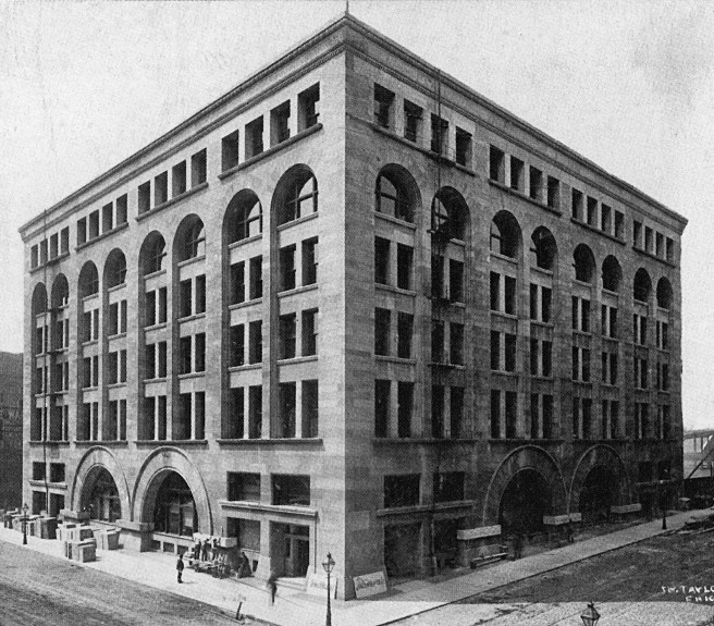
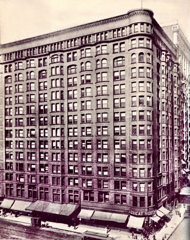
Burnham & Root, Great Northern Hotel, Chicago, northeast corner of Dearborn and Jackson, 1890. (Hoffmann, Root)
2. the skyscraper was simply a large, rectangular volume of space, therefore, the facade should be detailed so that it would be read as one continuous surface or enclosure of the interior volume (as if was wrapped in cellophane).
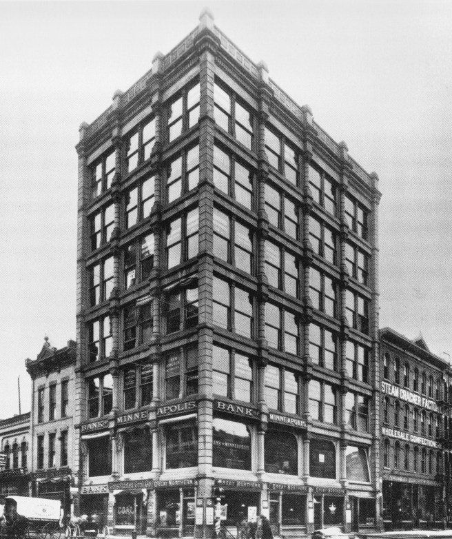
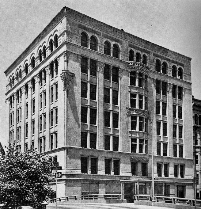
Hodgson and Son, Bank of Minneapolis, Minneapolis, 1885. (Millet, Lost Twin Cities)
3. the skyscraper consisted of an iron skeleton frame, therefore, the facade should express the rectilinear grid that results from the columns and the beams.
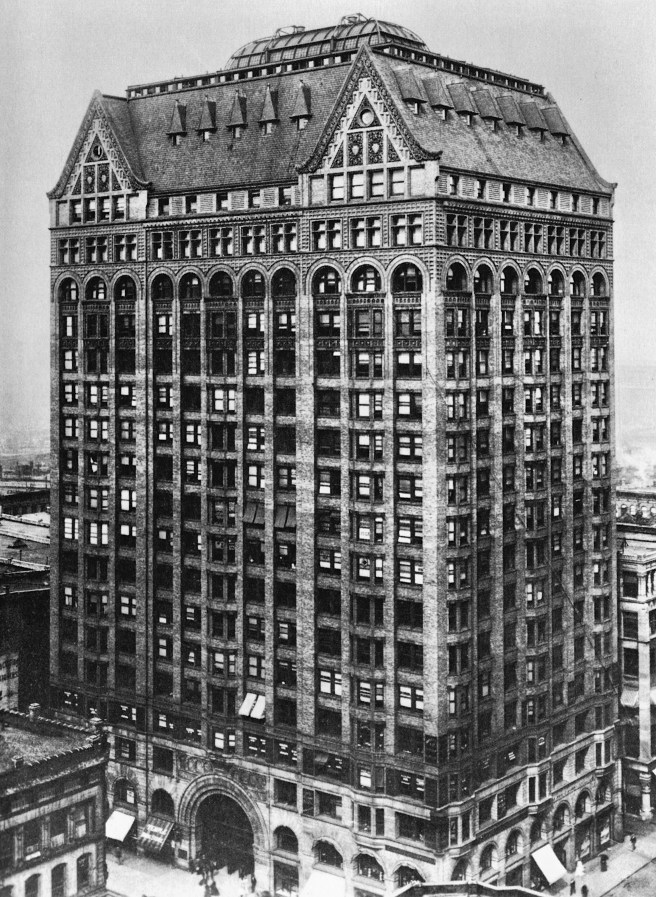
Burnham & Root, Masonic Temple, Chicago, northeast corner of State and Randolph, 1890. (Hoffmann, Root)
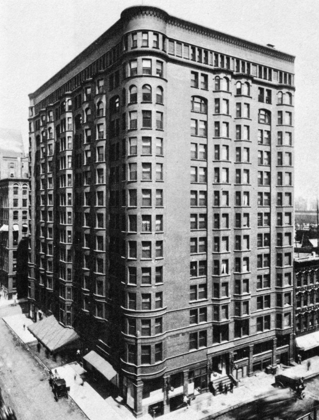
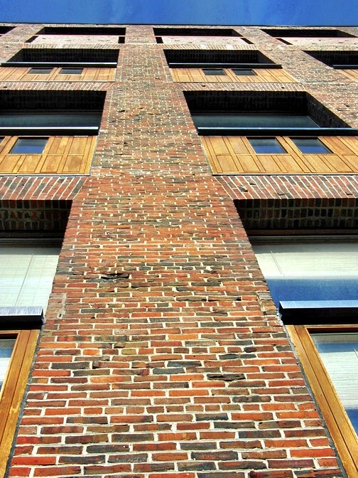
4. the skyscraper’s proportions were overwhelmingly vertical, so why not reinforce the skyscraper’s overall massing by accentuating its verticality through emphasizing the continuity of its columns). No one has better expressed this design approach to the skyscraper than did Louis H. Sullivan in 1896:
“What is the chief characteristic of the tall office building? And at once we answer, it is lofty… It must be tall, every inch of it tall… It must be every inch a proud and soaring thing, rising in sheer exultation that from bottom to top it is a unit without a single dissenting line.”
However, contrary to Sullivan’s dictum, there were at least four ways that American architects evolved in the 1890s to rationally design a skyscraper. As in most things in life, there would not be, there is not only one, right way to design a skyscraper. Claude Perrault dispelled such an idea in 1683 when he introduced the validity of the subjective/arbitrary in aesthetics in his Ordonnance pour les cinq sortes de colonnes d’après la méthode des anciens (Ordinance for the five kinds of columns according to the method of the ancients).
Richard Morris Hunt, Study for the New York Tribune Building, New York, 1873. (Online)
Both of these “artistic” approaches to the design of a skyscraper’s facade revolve around the issue of how to detail a window within the surface of the exterior wall. The rational approach found the artistic challenge in how to best express the building’s structural system and how to respect the integrity of the materials employed (influenced by the ideas of Pugin, Jones, Ruskin, Viollet-le-Duc, Semper among others).
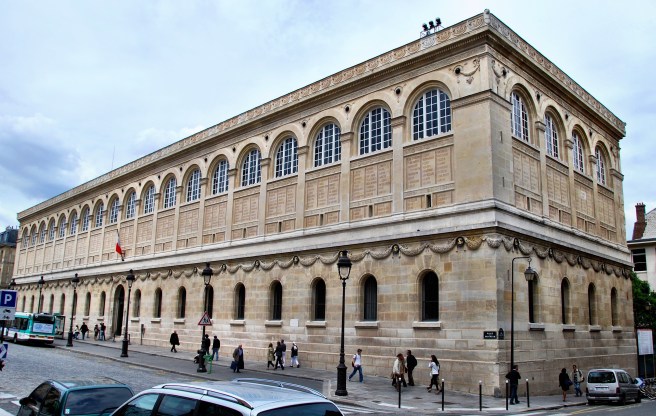
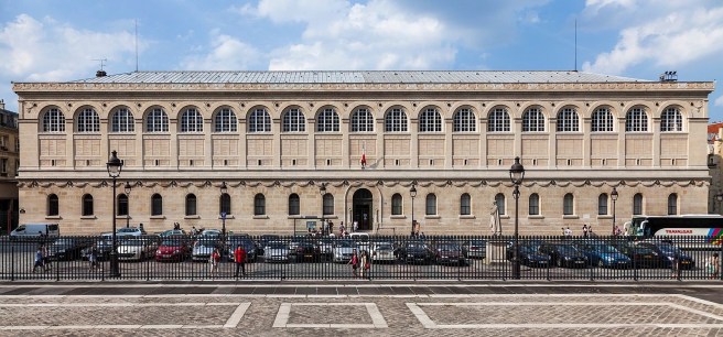
Henri Labrouste, Bibliothèque Sainte-Geneviève, Paris, 1838-51. (Author’s collection)
The primary formal or compositional concern was involved with visual or optical perception. Illusion would play a major role in the design of a skyscraper, especially in a design that wanted to look taller than it actually would be, for any number of reasons. Illusion simply means to make something look like something other than what it really was. Some of the favorite details of illusion in skyscrapers were:
-to make the vertical dimension of each floor slightly smaller than the one below it, thereby reinforcing the effect of perspective
-to group a number of floors together into one horizontal unit with sillcourses only at certain intervals, which then would give the scale of the elevation a different reading than what would result if the banding occurred at each floor. A traditional progression would be the lowest layer would have three floors, the middle layer would have two floors, and the top layer would have only one floor). I will abbreviate this type of progression as 3:2:1. (see Hunt’s early study for the Tribune Building above)
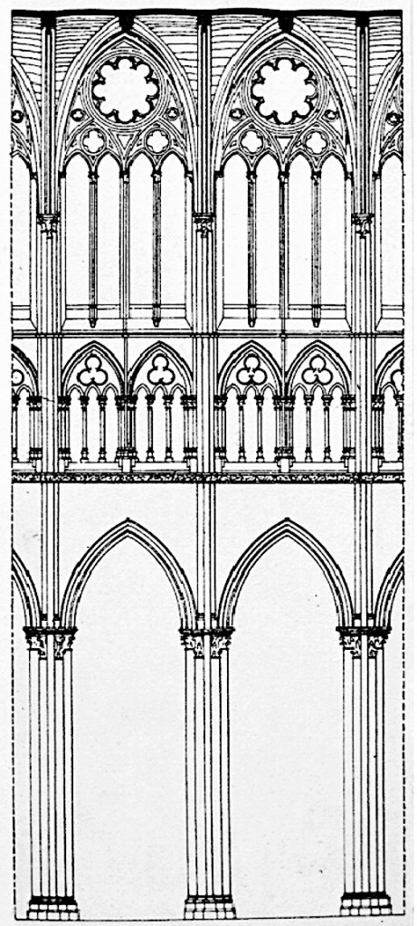
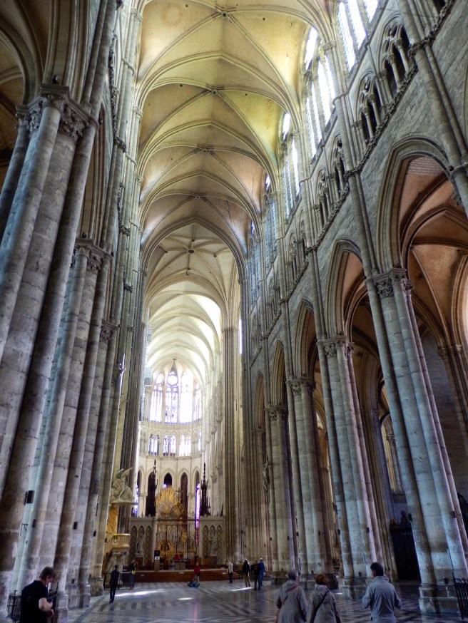
Amiens Cathedral, Nave Elevation. Note the progression of openings from 1:2:4. (Online)
-to make the windows in the upper floors smaller than those in the lower floors. This was usually done in some type of geometrical progression between the columns or piers of the building’s primary structural bays. A traditional progression, which dated back to the Gothic cathedral was one (in the base), to two (in the middle), to four (in the top). I will abbreviate this type of progression as 1:2:4.
Adler and Sullivan, Walker Warehouse, Chicago, southwest corner of Adams and Market, 1887. (Cannon, Louis Sullivan)
-to reinforce the perception of a skyscraper as a vertical object, the verticality of the facade could be complemented by giving the elevation a vertical emphasis, rather than a horizontal one, by eliminating all continuous banding. This could also be reinforced by grouping two or more windows in an unbroken vertical line by recessing the spandrel between the windows.
Burnham & Root, American National Bank, Kansas City, 1886. (Hoffmann, Root)
4.8. THE “RATIONAL” DESIGN OF AN ELEVATION
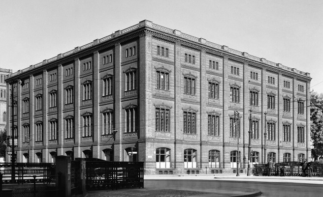
Karl Friedrich Schinkel, Bauakademie, Berlin, 1831. (Online)
As the skyscraper continued to grow taller and architects began to understand the subtleties involved in its design, architects who had been influenced by the writings of theoreticians who were exploring what a nineteenth century or modern architecture should be, began to experiment with a rational approach to the design of a skyscraper. (Arguments on either side of the issue whether or not a “rational” façade was a “modern” invention can be made, but this point is outside the bounds I have set for this blog.) One of the first reevaluations of traditional facade design involved the formal scheme of diminishing the size of the windows as one rose up the building used in the layering or progression of arcades or window sizes. When viewed through the filter of rationalism, this detail was actually counter to what an architect should be doing if he wished to express the structural qualities of the building, or in other words, express what the structure was doing. As the gravity load accumulated from the roof to the ground, more structure was required in the ground floor then at the top.
Louis I. Kahn, Phillips Exeter Academy Library, Exeter, NH, 1965. Note how the width of the brick piers from the top increase by eight inches at each floor. (Author’s collection)
In other words, the openings in a multistory building, if predicated on structural expression, should get LARGER as one rose up the building, because less structure was required in the upper floors than in the lower ones. Other rationalists, however, would counter this argument quoting the amount of daylight received by each of the floors in a skyscraper. From their standpoint, the lower floors of a building typically received less daylight than the upper floors due to shadows from buildings located across the street. The tradition of decreasing the size of the windows as one moved up an elevation, in their view, did have its basis in a rational design approach. This opinion was reinforced by the rational idea that a building’s windows should express the function of the space behind the window. For a typical skyscraper, the first two floors were prime rental floors, i.e., large, grand spaces and windows. The upper-most floor was typically reserved for mechanical equipment, that required small windows, with the body of the building comprised of the repetitive office floors.
Eventually as skyscrapers grew taller, however, the manipulation of the size of the windows became anachronistic because the number of floors had increased to the point where this idea was no longer perceptible or useful. Also by this time, the arched opening was a romantic daydream in a steel-framed skyscraper. Nobody had expressed the architect’s dilemma in the design of a skyscraper at the end of the nineteenth century better than Root:
“Think of the feelings of an Athenian architect of the time of Pericles to whom the problem should have been presented to design a building of fourteen stories, imposing upon him the following conditions: all of the stories except two to be 10 feet 6 inches high, all window sills to be exactly 2 feet from the floor, all lintels to be 6 inches from ceilings, and all windows to be in width not less than 4 and not more than 6 feet, and to be situated at distances apart of not more than 6 feet. If these conditions did not paralyze the architect, give him a few more: that all windows should have flat lintels, and that he must avoid as much as possible all projecting members on the facade, since these catch dirt and soot; and give him instructions to put on a few ten-story bay windows.”
Burnham & Root, Chicago (Great Northern) Hotel, Chicago, northeast corner of Dearborn and Jackson-diagonally across from the Monadnock, 1890. (Hoffmann, Meanings)
When faced with the design of the elevation of a “wall” building, an architect had two variables to manipulate:
1. How to design the surface of the wall:
a. treat the multistory wall as a smooth, unbroken plane,
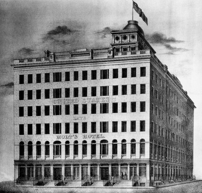
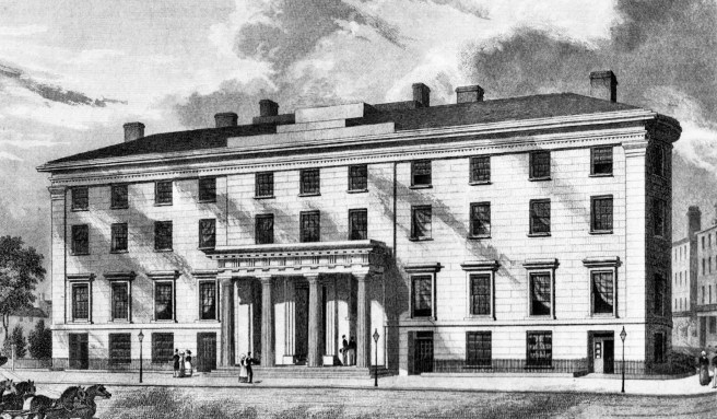
United States Hotel, New York, 1832. (Landau and Condit, New York)
b. or express each floor with some type of band of ornamental molding, usually referred to as stringcourse. (It is called a sillcourse if it is located at the base (sill) of the windows,
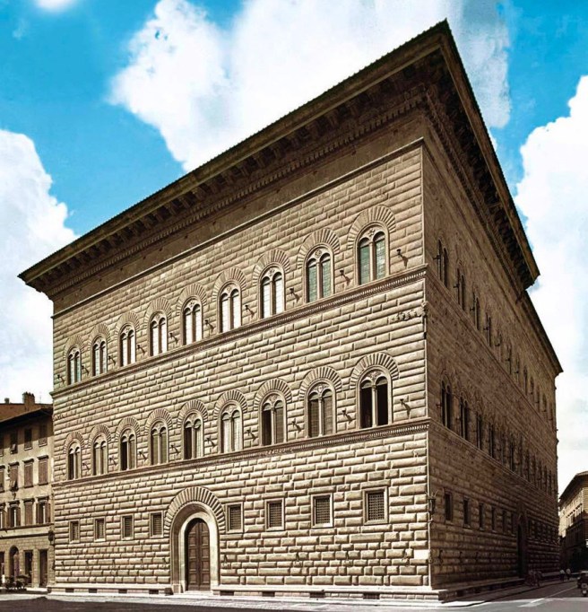
Giuliano da Sangallo the Younger, Palazzo Strozzi, Florence, 1489.
(Online)
c. or compose the design of the elevation of the wall in relation to some preconceived theory or style, such as the tripartite composition of a classical column. Buildings whose middle bodies contained more than three floors would typically have these floors grouped together into one larger scale layer by the use colossal pilasters or the multistory arcade.
George B. Post, Mills Building, New York, 1881. (Landau, Post)
George Post, Proposed Design for the Marine Bank, New York, c. 1874. (Landau and Condit, New York)
2. How to design the windows in the wall:
a. repetitive, make every window the same,
Trench & Snook, A.T. Stewart’s “Marble Palace” Department Store, New York, 1845. (Landau and Condit, New York)
b. or compose the design of the windows in the wall in relation to some preconceived idea.
George Post, Produce Exchange, New York, 1881. Detail of arcaded elevation. Note how he respects the integrity of each arch: the lower arches have triple windows, the upper arches have one semicircular piece of glass. He does not split the curved space in two with a mullion that looks like a support under the center of the arch. (Andrews, New York)
The repetitive window solution was a logical solution, because in a skyscraper all the floors are the same. So what justification could there be for an architect to vary the sizes or shapes of the windows? If an architect attempted to compose the building’s elevations, by manipulating the windows in some manner, it obviously was not because of logic, because logic dictated that all the windows should be the same. The reason, therefore, would have been art. Here, then is the nub of the problem with the design of a skyscraper (or any building, for that matter). If one aspires to make architecture, by transcending the act of building, is there only one way to be “artistic,” or does one have a choice in how to be “artistic?”
4.6. THE ART OF DESIGN: FORMAL VS. RATIONAL
Left: Karl Friedrich Schinkel, Bauakademie, Berlin, 1831. (Online); Right: Henri Labrouste, Bibliothèque Sainte-Geneviève, Paris, 1838-51. (Author’s collection)
I find the answer to this enigma once again in an analogy with literature. Is a great novel a work of art? Of course, it is. Is a great poem a work of art? Likewise. They both are literature. They use the same media, words. They both have the same function, to express an idea. So while they are related, they also are different, are they not? In the English language, we differentiate between these two methods of using words with the terms “poetry” and “prose,” or “poetic” and “prosaic.” One is not more “artistic” or more challenging than the other, is one? Unfortunately, the word prosaic has evolved a separate definition of unimaginative or dull, so it does not evoke the same emotions today as does word poetic. So what terms should I use to differentiate between an architecture that tries to be “artistic” with the logical aspects of a building, and an architecture that tries to be “artistic” with the compositional aspects of a building? Having an affinity for alliteration, four pairs of words come to mind:
Prosaic vs. Poetic
Logical vs. Lyrical
Rational vs. Romantic
Functional vs. Formal
Architectural theory has traditionally chosen “formal” and “rational” (note that I use an alphabetical order) to describe these two approaches to the design of a building, and so I will use these two terms, keeping in mind that they are not always mutually exclusive. Throughout the history of architecture, there have been traditions of both approaches, so neither could be labeled as innovative in the nineteenth century (as seen in the first two images). As with poetry and prose, one is not inherently better or more difficult than the other.
The building’s exterior form we have discussed at some length under “commodity.” The form of the major portion or body of the skyscraper was determined from an intense study of what was the best configuration for the typical office floor plan, based on maximizing rentable floor area and how it was to be daylighted. Once a plan had been finalized, it simply was extruded vertically for either as many floors the owner wanted or to the maximum height allowed if a building or zoning code had been enacted at the time of design. The body of the building, thus configured, would be placed on a base that sat on the ground. As opposed to the body that at times could break away from the plane of the lot line whenever a lightcourt came into play, the base of these skyscrapers always held to the lot lines, so as to maximize the amount of rentable floor area in this high-rent zone. This also applied to the basement, where the need for space continued to grow as buildings became more mechanized and the basement was a logical location for the equipment. Banks, public offices of major companies, and stores were the standard tenants not only for the ground floor, but also in many cases, for the second floor (typically referred to as the entresol or mezzanine) as during this time one flight of stairs was not viewed as an impediment.
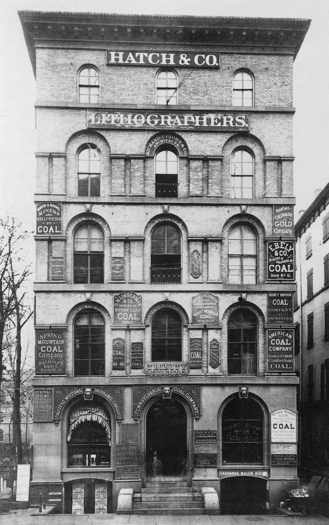
Richard Upjohn, Trinity Building, New York, 1851. (Woods, From Craft to Profession)
Tradition dictated that the building’s elevation be symmetric about a central axis (this assumes that the lot was big enough to accommodate such a plan that was not always the case). This was reinforced by the introduction of the elevator that wanted to be centrally located to minimize walking distances to either end of the corridors. This typically resulted in the entrance being placed in the middle of the elevation. Sometimes the main entrance was marked simply by a door placed in the center window on the ground floor facade, or an architect might insert a triumphal arched entry at this point.
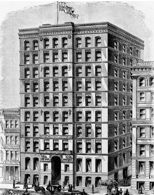
Burnham & Root, Montauk Block, Chicago, 1881. I chose the Montauk Block also to show the asymmetrical location of the entry caused by a small-sized lot. (Andreas, History of Chicago)
A third alternative for the entrance was the addition of a portico or architectural canopy that projected in front of the body of the building.
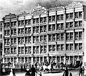
The center of the building could also be marked by either by the addition of a pediment at the building’s cornice or the slight projection/recession (see top image) of the central portion of the wall relative to the flanking ends of the wall.
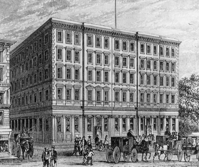
Stephen Hatch, Boreel Building, New York, 1878.
(Online)
One of the major design issues that divided the European styles that were used in the early skyscrapers into two camps was the design of the roof. Was it necessary to see the roof from the ground, or was the building to be a simple box with four walls? The Italian palazzo and the German Rundbogenstil styles were primarily a “wall” architecture, with no visible roof so the vertical plane of the wall was the primary visual element to be seen, and therefore, designed. The British Victorian Gothic/Queen Anne and the French Second Empire styles celebrated the roof as the culmination of the building’s massing; the Second Empire style requiring its particular type of roof, the Mansard, to be incorporated into the design, even if it was merely a fake sloping wall of the top floor. Buildings with a roof compounded the design theory of the tripartite elevation (a top, a middle, and a base). The European Classical tradition dictated that the elevation of a building should be treated like that of a classical column, that is, it should have a base or bottom, a shaft or middle, and a capital or top. With regards to the tradition of the tripartite elevation, was the roof to be incorporated with any portion of the top floor as the “cap” or could a roof be added to a wall that was already designed into three parts, thereby adding a fourth element to the elevation?
4.4. THE ELEVATIONS: OPENINGS IN THE WALL
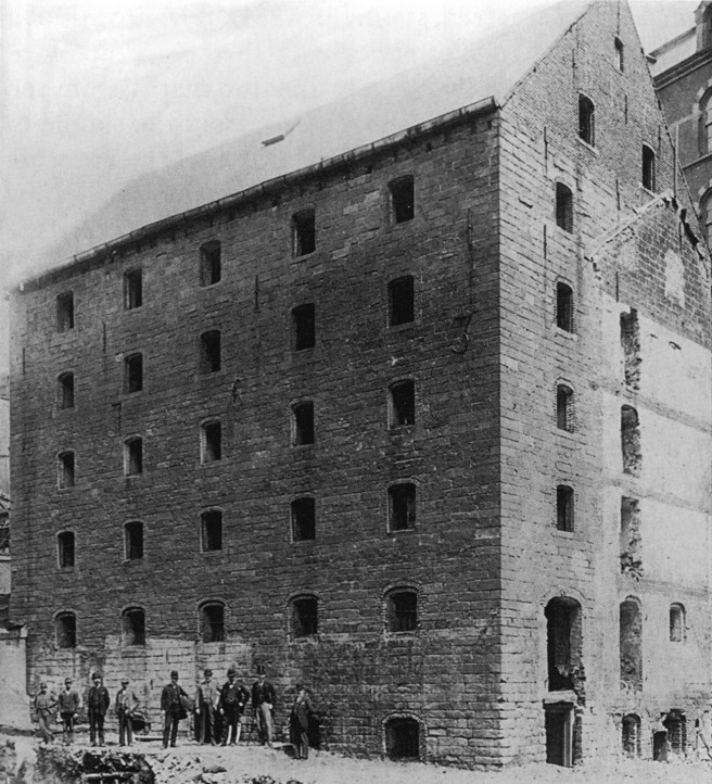
Rhinelander Sugar House, New York, 1763. (Stern, New York 1880)
It is this next design issue, the articulation of the building’s exterior wall, elevation, or façade that would be the most challenging in the evolution of the skyscraper. As there were no precedents from the past to inform the designer facing the problem of a ten-story skyscraper, invention would necessarily have to play a significant role in the design of a skyscraper’s exterior elevation. The problem an architect faced is simply put: how to detail holes (windows) in a wall. The artistic challenge was the “how.”
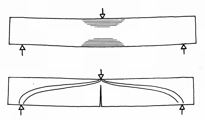
Bending Stress in a Loaded Beam. Compression in the top of the beam is offset by the tension developed in the bottom of the beam. Materials, such as stone, that have a low resistance to tension will crack, as shown in the bottom diagram. (Mainstone, Developments in Structural Form)
Historically (traditionally), making an opening in a stone or masonry wall was controlled by the manner in which an architect chose to cover the opening in the wall. If using stone, as long as the stone available was long enough to span the opening, a horizontal beam or lintel could top the opening that generated a horizontal or flat-headed opening. That is, as long as the stone’s tension strength was not exceeded, for the stone was a beam that would deflect in the center due to gravity. This deflection caused the bottom of the beam to elongate or stretch, generating considerable tension, that eventually could exceed the stone’s tension strength. If this happened, the stone would crack and collapse into the opening below. Wood has a much larger capacity to resist tension, and therefore, can span farther than stone, but wood is not always resistant to fire, and therefore, could not be used. In order to span greater distances than the limit of a stone beam with a fireproof material, the arch was developed (this happened long before the invention of cast iron).
Thrust Generated in a Multiarched Arcade. Note that the thrust of one arch is offset/butressed by the opposite thrust of the adjacent arch, except at each end of the arcade. At this point a buttress, larger than the interior piers that support the arches is required to resist the thrust. (Online)
The arch is a structural element that due to its shape, remains in pure compression. Stone has a very high compression strength, therefore, a stone arch has no real limit as to how far it could span, as the Pantheon in Rome (148′) reveals. There are two inherent differences an architect had to deal with when he used an arch as opposed to a lintel to cover an opening or window. First, the shape of the head of the window could be curved in any number of ways (shallow segment of an arch to a pointed arch), including a flat-arch. Second, an arch generates thrust, a horizontal force that tends to push the supports of the arch apart from one another. A lintel does not develop any thrust, so in a wall that uses beams, the corner columns can be the same size as the interior columns. Not so with a wall that uses arches. While the thrust from adjacent arches offset each other, the column at each corner does not have an adjacent arch, and therefore, must be larger than the other columns to resist the thrust of its arch. One could make a visual analogy with a picture frame. A wall that uses arches to span its windows requires heavier corner columns/piers that create a frame on both ends of the wall or facade.
Henri Labrouste, Bibliothèque Sainte-Geneviève, Paris, 1838-51. (Author’s collection)
To support the gravity load of a building, architects and builders had a choice of one of two systems: either vertical walls (plane/surface) or vertical columns (lines). Hence, the exterior of an early multistory building would consist of either a repetitive stacking of columns and beams or a wall plane punctured with window openings, be they flat- or arch-headed. The column/beam option was initially the more expensive option because it was harder and more expensive to construct, so most builders turned first to the wall with openings to support the multi-storied building.
Park Row Stores, New York, 1850. (JSAH, October 1972)
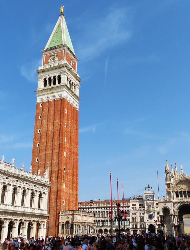
Companile, St. Mark’s Cathedral, Venice. (Author’s collection)
As Root sat at his drawing board in early 1880, mulling over the ideas he was developing for the exterior for the Grannis Block that Owen Aldis had commissioned, his first multistoried building, his mind would have quickly reviewed prior buildings that he was familiar with, whether they were from the past or the present, including those he had just seen in the latest magazines. His next project for Aldis would be the 10-story Montauk Block, generally agreed to be Chicago’s first skyscraper, so I am just going to blur these two buildings into one process: the design of a skyscraper.
What should a skyscraper look like, and, more importantly for Root, as an artist, how should an architect design a skyscraper? (What I mean by design is, instead of just erecting a 10-story building as a contractor might build a factory, an architect must have an artistic/theoretical concept/idea to achieve in the design. In literature, this is referred to as a theme or plot.) As a new type of building, the problem of designing an early skyscraper presented a nineteenth architect architect with a quandary. There was no tradition of designing a 10-story building. There were no prior skyscrapers, or precedents, that an architect could turn to for inspiration or direction in how to design it. For an art that by 1880 had relied upon the traditions and precedents of the past not only as the point of departure in the design of a building, but also as the yardstick against which to measure the quality of the final product, one was literally dumbfounded as to where or how to begin, as Root honestly related in 1890:
“Looking at the problems presented by these buildings… we may certainly guess that all preexisting architectural forms are inadequate for their solution, and that no logical combination of those forms can be made efficient without changes so great as to be practically destructive.”
4.1. HISTORIC PRECEDENTS OF TALL STRUCTURES
Going back to the history books to find examples in the known Western world, an architect might find inspiration for the design of a tall structure in the following periods:
1. Egyptian: the obelisk was a vertical structure.
2. Greek: the Lighthouse at Alexandria was reputed to have been the tallest structure in the ancient world with a height estimated between 375′ and 450.’ The Mausoleum of Halicarnassus was the other well-known tall structure of the era estimated to have been 135′ tall.
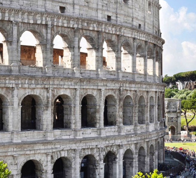
3. Rome: although Rome had built apartment buildings that were 5-6 stories high, the exterior of monumental buildings such as the Colosseum and the Pantheon were treated in a similar manner. Their exterior elevations comprised of horizontal layers of one-story tall engaged pilasters carved into the marble veneers that were applied one on top of another to their masonry structures.
Colosseum, Rome. (Online)
Similar to the Egyptian obelisks, Rome also built a number of monumental columns, the best known being the Column of Trajan and the Column of Marcus Aurelius, the height of each topped off at around 100.’
4. Byzantine/Romanesque: the bell towers (campanile) of the new Christian churches were a new type of vertical structure. The best-known being St. Mark’s in Venice and the leaning structure at Pisa.
5. Gothic: the Gothic Cathedral can easily be understood as the first “vertical” style of architecture. That is, instead of stacking one horizontally accented layer of building on top of another, the Gothic nave, directing the eyes of the viewer towards heaven to make a direct connection with God required a dominant, unbroken vertical accent in the building’s interior elevations, that eventually was continued into the building’s exterior.
Amiens Cathedral. (Author’s collection)
4.2. AMERICAN MAINSTREAM ARCHITECTURE IN 1880
In Volume Two, Section 1.5 I reviewed the state of American Architecture in 1880 and had summarized it in both the East and the West (Midwest), before the parting of the ways in 1884, using my combination of John Summerson’s and Barry Bergdoll’s taxonomies as Eclectic/Pluralistic. As proof of this, I offered the AIA’s first list of Top Ten American buildings, that included examples of Richardsonian Romanesque, Victorian Gothic, Gothic Revival, and French Châteauesque. I would categorize the styles then in vogue along their ornamental details as:
1. CLASSICAL:
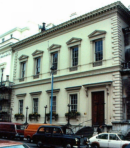
British: Neo-Renaissance Palazzo
Charles Barry, Travellers’ Club, London, 1829.
(Online)
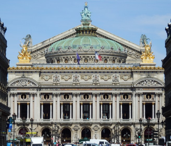
French: Neo-Baroque 2nd Empire
Charles Garnier, Paris Opera House, 1861-75. (Author’s collection)
2. GOTHIC:
British:Victorian Gothic
George Gilbert Scott, Midland Hotel, in front of St. Pancras Station, London, 1865. (Online)
French: Gothic Revival
Eugène-Emmanuel Viollet-le-Duc, Entretiens sur l’architecture, volume I, 1863. Apartment building with iron corbels and ceramic tile facade. (Midant, Viollet-le-Duc)
3. ROMANESQUE:
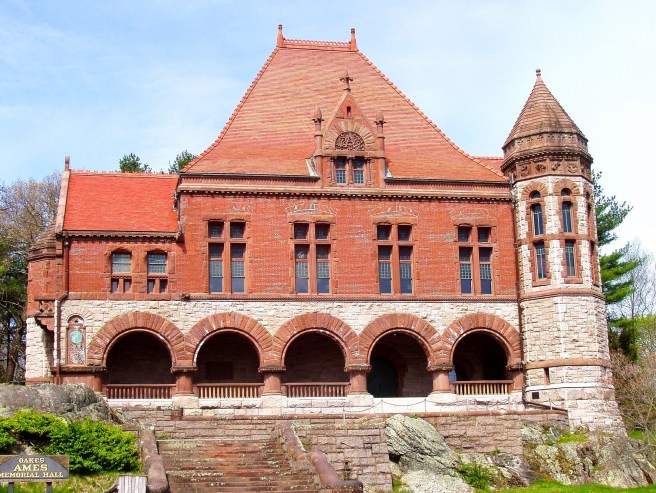
American: Romanesque Revival
H.H. Richardson, Townhall, North Easton, Mass, 1879. (Online)
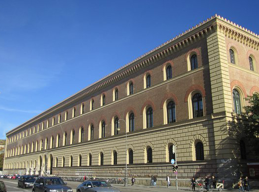
German: Rundbogenstil
Rundbogenstil: Friedrich von Gärtner, Bavarian State Library, Munich, 1831. (Online)
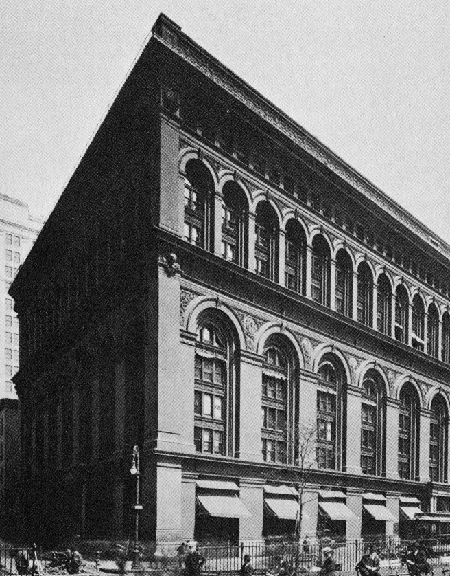
George B. Post, Long Island Historical Society Building, Brooklyn Heights, 1878. (Landau, Post)
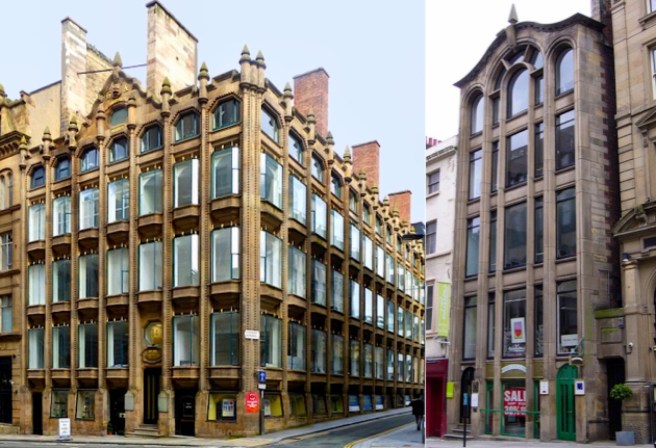
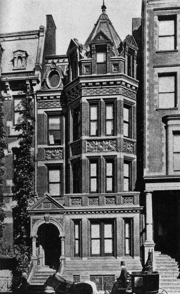
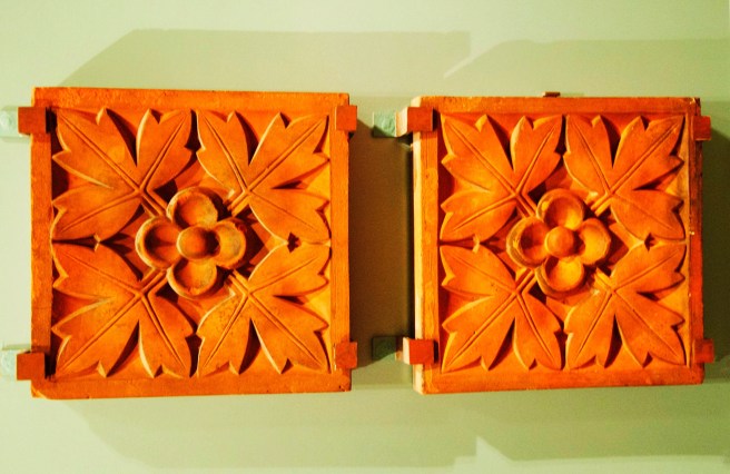
I have noted the continuous collaboration between George Post and Peter B. Wight, before and following Wight’s move to Chicago, so there is no doubt in my mind that Wight would have taken the opportunity to introduce Post to Loring’s ornamental terra cotta. Also, as an active member of the A.I.A. Post should have been familiar with the achievements of Loring. Late in 1877, Loring received his first contract for architectural terra cotta in New York through Post. Therefore, as far as I can determine, Post was one of, if not the first New York architect to follow the lead of Chicago’s architects by incorporating ornamental terra cotta in the exteriors of his buildings. His first use of Loring’s terra cotta was in a house at 15 East 36th Street that he designed for the Danish consul, H.M. Braehm. Loring’s Boston works produced the large, four-foot high terra cotta panels that were inserted beneath the window openings. The terra cotta panels were made with a red clay that matched the red pressed brick he used for the exterior. Post had chosen in this building to depart from his earlier polychromatic excursions by experimenting with an avant-garde monochromatic palette of materials (that was more than likely influenced by Richard Morris Hunt’s early, unbuilt monochromatic scheme for the Tribune Building (see next Section).
George B. Post, H.M. Braehm Residence, New York, 1877. (Landau, Post)
While Post was completing the design of the Braehm house in 1878, he was also engaged in a design competition for a building for the Long Island Historical Society (that we will discuss in the next Section). He had incorporated an arcade in the final design in which he began to exploit the decorative potential of Loring’s material. This monochromatic design took his experiment in the Braehm House to the extreme by eliminating all contrasting banding. Pressed red brick piers framed and supported red terra cotta arches, spandrels and stringcourses that were fabricated at Loring’s Boston works. This discussion borders on the third Vitruvian requirement, “Delight,” that we will explore in the next chapter.
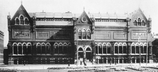
Sturgis and Brigham, Museum of Fine Arts. Terra cotta tiles manufactured by John Blashfield. (Boston Museum of Fine Arts)
As earlier noted in Dr. Cutting’s 1880 report, it was perceived that good building practice dictated that even decorative stone trim should be eliminated from brick walls, due to the potential damage likely to result from the stone’s exposure to heat. Therefore, an architect who wanted to impart some type of ornamental relief to a brick wall had to either employ a variety of coursing patterns (as we saw in Furness’ designs) or actually have the brick sculpted in place. This latter practice was quickly supplemented with the use of molded brick, but the high degree of intricate carving inherent with stone was still lacking in these brick techniques.
The need for a highly plastic material that could withstand not only the rigors of the North American climate, but also the high temperatures generated by a fire, had already been resolved in Chicago after the 1871 fire with Sanford Loring’s development of architectural terra cotta. While I have reviewed Loring’s development of porous terra cotta (fire clay tile) as a fireproofing material, I have not delved into his earlier pioneering efforts to fabricate an American ornamental terra cotta. During his partnership with William Le Baron Jenney (1868-70), Loring had become involved with a small terra cotta company in Indianapolis that had been purchased in 1868 by Chicagoan J.F. Nichols that he had moved to Chicago. Loring had dissolved his partnership with Jenney in the spring of 1870 so he could devote his efforts solely on improving the quality of the company’s products. Concerned about the quality of their product and aware that England at this time had overtaken France in the quality of its architectural terra cotta, Loring wrote to the largest English terra cotta company, owned by John M. Blashfield in Stamford, Lincolnshire, and eventually secured the talents of the company’s foreman, James Taylor, who arrived in Chicago in August 1870. This was a stroke of good fortune for Chicago’s architecture, for upon his arrival in New York in the spring of 1870, Taylor had first tried to secure financial backing to start his own company. Luckily for Chicago, Taylor found the minds of New York’s architects closed to his ambition:
“My dear sir, there can be but one opinion upon that subject. It would most surely fail. has been tried over and over again, and every attempt has resulted in loss and vexation to all parties concerned. We know all about that material; it is useful enough in Europe, but it will not withstand the rigors of our American climate. If that young man intends to continue his trade of making I would strongly advise him to return to England, for he will find it impossible to earn a living for his family at that trade in the United States.”
Therefore, Taylor had no alternative but to move on to Chicago, for:
“In 1870 the New York architects and builders certainly were not ready for the reception or use of architectural terra cotta, and therefore no organized effort was made at that time to manufacture it in this vicinity… The first American city to welcome architectural work was Chicago. The Western metropolis teems with men who, like the Athenians of old, are ever on the lookout for some new thing. The cost of stone, the rusting of iron and the danger of wooden structures to city property led them to cheerfully welcome a material that would… give them a decorative and useful building material.”
Adopting the English improvements Chicago Terra-Cotta’s products immediately improved to a quality that began to support architectural applications, fortunately just in time for the post-fire building boom. Taylor also appears to have changed the company’s design emphasis from that of imitating stone to one that exploited and expressed the inherent plastic qualities of terra cotta.
While Chicago Terra-Cotta had already provided terra cotta for over 300 buildings in the Midwest by the time of Taylor’s departure from England early in 1870, Blashfield had just shipped to Boston his first terra cotta produced for an American building. John H. Sturgis, a Boston architect who had been in England since 1866, had gained a firsthand knowledge of the developing English technique that apparently paralleled Loring’s mounting interest. In 1869 Sturgis had designed “Pinebank,” the Edward N. Perkins House (grandson of James Perkins, T. H. Perkins’ brother and partner in Boston’s largest China trade firm) in Boston that was erected early in 1870. Sturgis contracted Blashfield to produce a terra cotta parapet and ornamental panels that were carefully shipped to Boston for the house. Thus, the East Coast had received its first significant example of English architectural terra cotta not much later than Loring’s first applications in Chicago using the English improvements by Taylor.
Sturgis’ interest in terra cotta may have been one of the factors that led to his firm’s (Sturgis & Brigham) winning the competition in February 1871 for the Boston Museum of Fine Arts to be erected on Copley Square (where the 1867 Temple of Peace had been erected). The successful use of terra cotta and molded brick in Perkin’s house, who coincidentally was the chairman of the Boston’s Athenaeum’s Fine Arts Committee that had originally proposed the museum, probably lent credence to Sturgis’ entry that incorporated terra cotta on a large scale for the first time in the East. While working on the final design and coordinating the terra cotta details with Blashfield, who was, once again, contracted to produce and ship it to Boston, Sturgis took the opportunity to share his knowledge of English terra cotta at the 1871 A.I.A. convention in a paper that coincidentally preceded Wight’s observations of the Chicago fire. After giving a brief history of the material, Sturgis listed three major advantages of terra cotta: it weathered better than any other material, including stone; it was not only cheaper than carved stone, but could be produced in quantities at a faster rate; and lastly, it weighed much less than stone that meant not only that it was easier to transport and erect, but also the load imparted to its supporting structure was much less.
Sturgis and Brigham, Museum of Fine Arts, Boston, 1870-76. (JSAH, May 1973.)
Unfortunately, it wasn’t until 1874 that the Boston Museum’s construction began. First, the Boston fire of November 8-9, 1872, and then the financial Panic of the following September, kept postponing the start of construction on the Museum, which didn’t open until July 3, 1876, some five years after Sturgis and Brigham had been awarded the commission. By this time, Sturgis’ successful incorporation of Blashfield’s terra cotta in the building had made the city a prime potential market for the introduction of Loring’s product in the East. Following the completion of the Museum in July 1876, after almost six years of successful exterior applications of architectural terra cotta in Chicago, Loring took advantage of three large orders from Boston for ornamental terra cotta and made arrangements to rent a portion of the Boston Fire Brick Co. facilities in order to start up a second factory. This was not only a more feasible arrangement than trying to transport such a large quantity of finished terra cotta over such a distance (although it had been done before), but more importantly, it also afforded a base office from which to expand the company’s business in the region of the country where the Depression was first letting up. Fortunately, Loring was able to entice his former foreman, James Taylor, who had just retired to New Jersey in early 1876, to supervise the new operation. Loring himself also moved to Boston to aid in the start-up and to procure new contracts. such as in Philadelphia, (Christ Church Chapel designed by J. P. Sims in 1876) and In Providence, Rhode Island.
Burnham and Root, The Rookery. Exterior Lightcourt. (Author’s collection)
The only solution to overcome this inherent limit to Chicago skyscrapers was to invent a system of fireproof construction that weighed less per floor than did traditional masonry construction, so that the foundation pressure remained below 3000 psf as skyscrapers grew taller and taller. This is the true genius behind the invention of “Chicago construction:” taller skyscrapers that actually weighed less than their shorter, bearing-walled brethren. While Wight’s system had solved this problem with interior iron framing, it would take another six/seven years following Wight’s triumph in the Boston Architects’ test in 1881 before iron columns finally replaced a skyscraper’s exterior masonry bearing walls. Because of the complexity of engineering and in constructing a ten+-story building, in addition to the municipal building codes that required masonry walls all along a building’s exterior perimeter for protection from an adjacent fire, the change from “boxed construction” to “framed construction” would be a cautious trial-and-error, step-by-step process during the years 1885-1890.
Post, Equitable Building. Banking Hall as it appeared in 1889. (Landau, New York)
We will see the first tentative experiments in exterior iron framing will occur in the exterior walls of the interior lightcourts of skyscrapers that had no such restrictions (remember Post’s detailing in the lightcourt walls of the Equitable Building). This legal loophole had simply reinforced the practical reason for employing iron framing in these locations: these exterior walls were supported above a major space of the ground floor that wanted to be as open as possible. Therefore, the weight of the lightcourt’s walls could not be supported by carrying a bearing wall all the way to the ground floor but had to be transferred at the second or third floor to a series of beams that were then supported by columns. So if the weight of the lightcourt’s exterior walls was going to be transferred to a series of beams, why not try to make the walls as light as possible in the first place, and simply carry the iron framing of the first and second floor up, into the exterior walls of the lightcourt? This was rather straightforward to detail and easier to do than immediately experimenting with iron framing in the exterior walls because the weight and rigidity of the exterior masonry walls was still needed to resist the force of the wind (the wind is a horizontal force, so this quality of a building’s structure is referred to as lateral stiffness or bracing). Nevertheless, it eventually had to be done if the building’s overall weight was to be sufficiently reduced so that it could be built taller than 10 floors in Chicago. In solving this problem with the skyscraper’s exterior construction, Chicago again invented, or rather, perfected, a new material to reduce the weight of the exterior wall: architectural terracotta (this is a different product from fireclay tile). These are the reasons for this type of construction during the 1880s being called “Chicago construction.”
3.27. THE NEED FOR LATERAL BRACING
Once the skyscraper’s weight had been reduced by “Chicago construction,” the skyscraper could resume its upward growth. As soon as it did, however, it immediately ran into a new structural problem that had to be solved. As long as a building was constructed with load bearing masonry walls, the building’s weight, while being a negative with regards to the foundation issue, was a positive (its inertia) in resisting the wind’s pressure. The weight and the stiffness of the masonry simply meant that there was little, if any horizontal deflection in the upper floors, even on the windiest of days. Once that weight and stiffness was removed with the use of iron framing, things began to move rather noticeably. Making the building taller not only made it more flexible, it also added more wind pressure, i.e., it made a bigger “sail.” One of my favorite anecdotes from this period that pertain to the significant increase in building deflections in the early framed skyscrapers to which we can no longer relate, were the problems that people had keeping accurate time in the upper floors, because the excessive deflections wreaked havoc with the pendulums of the clocks. Another was the problem office workers experienced with their ink wells on windy days.
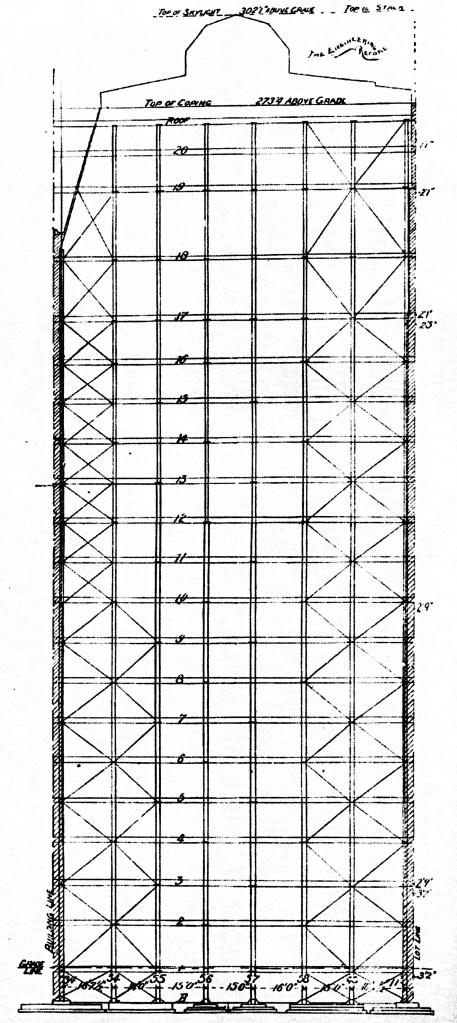
Burnham & Root, Masonic Temple, Chicago, 1890. Cross section showing the configuration of the diagonal bracing. Note the total height at the top of the building reads: 302’ 1.” (Engineering Record, January 21, 1893)
The problem of stiffening a framed building with regards to wind deflection was only highlighted by the great Charleston earthquake of August 31, 1886, still the largest quake ever recorded in the southeast. It was large enough that it was felt even in locations as far away as Chicago. The earthquake gave architects and owners alike, pause to reconsider the ramifications of removing those heavy, stiff walls… The solution to the deflection problem of the iron skeleton framed skyscraper was two-fold. First, builders incorporated diagonal bracing to impart a geometric stiffness (triangulation) to the frame. Second, the connections between the beams and the columns would be made stiffer through a combination of replacing bolts with rivets, and the use of gusset plates at the connection (that was referred to as portal framing).
Holabird & Roche, Old Colony Building, Chicago, 1893. Diagrams of Portal Bracing. The left shows a Phoenix column at each end with steel gusset plates riveted between the columns and beams. (Condit, Chicago School)
A stepped or pyramidal stone footing. (Left: Author collection; Right: Baumann, Foundations)
Third, and most important for skyscrapers in Chicago, was the fact that the sheer weight of the massive wall would create its own self-imposed height limit. This was due to the nature of Chicago’s underlying geology. Sufficient bearing capacity (3000 pounds per sq. ft) was immediately available for the first 12′-15′ of depth below grade. Below this stratum, however, the soil had a much weaker bearing capacity, which meant that foundations in Chicago had to be located within this first layer of good bearing. This posed an additional problem for builders in Chicago to which I will return to later. The self-imposed height limit for a masonry bearing wall was determined by the limited capacity of the upper layer of soil. At 3000 psf, a masonry bearing wall could be built only to a height of 10 stories, without resulting in excessive settlement. I said excessive because all buildings in Chicago at this time settled over time. The walls were built on pad foundations, that once loaded with the weight of the building, would put 3000 pounds per square foot of pressure on the ground that would eventually compress the ground accordingly, and the building would lower or settle over time. The settlement was a fact of gravity and physics. It couldn’t be eliminated, but the goal was to have even settlement across the length and depth of the building, or the building would experience differential settlement and the masonry would crack. I’ll return to this issue at a later time as well. The settlement was an accepted fact in Chicago, so much so that the sidewalks adjacent to a tall building under construction were typically built with a one to two inch slant up to the building, so that as the building completed its settlement over time, the sidewalk would settle with the building and would end up being level.
John Wellborn Root. Railroad rails used to replace layers of stone in a foundation, 1885. (Hoffmann, Root)
How this phenomenon created its own 10-story height limit was simply the fact there was also a limit to the area that a footing (a building’s foundation comprised of a number of footings) could be made. Prior to Root’s invention of the iron reinforced concrete pad footing during the winter of 1885/6, footings for buildings were built as stone pyramids, a shape that spread the concentrated load of the wall or column above to the weaker soil below. As gravity disperses force (the weight above) in a material at a 45° angle, the height of a conventional pyramidal foundation grew taller as the weight it supported corresponding increased. As the depth of the good bearing layer in Chicago in which this footing was located was limited to under 15’, the overall height of the pyramid was also limited to under 15.’
Adler & Sullivan, The Auditorium. Diagram of foundation. (Online)
That is, if the footing was to be kept within the basement, without shooting its top into the ground floor. This area/height limit equated to being able to safely transfer the load of a 10-story bearing wall. Therefore, once the maximum size of the footing had been reached, any extra load which resulted from additional floors would simply increase the bearing stress beyond the 3000 psf limit and result in significant settlement (the 17-story tower of the Auditorium Tower settled almost 28”) unless the pyramidal footing was made sufficiently large in area to keep its bearing pressure at 3000 psf. Of course, as the pyramid grew in area, it also had to correspondingly grow in height. As it could not be buried any deeper than the 15’ limit, this would require that the pyramid would project out of the ground floor and into the first story that, of course, was unacceptable. But owners still needed or wanted to build taller buildings in Chicago than ten stories. The taller buildings meant that the long-tem settlement of the building would be excessive. The worst example was the tower of the Auditorium whose eventual settlement was such that one would have to walk down three new steps to the ground floor that had to be added at a later date. (This excessive settlement was partially the result of a number of issues, including the addition of extra floors after construction of the foundation had already begun.)
Adler & Sullivan, The Auditorium. Photo showing the three steps added in the ticket vestibule following the Tower’s settlement of almost 28.” (Author’s collection)
Construction of the Washington Monument, Washington, DC. (Author collection)
The tallest example of a masonry bearing wall structure is the Washington Monument, started in 1846 and completed at a height of 555′ in 1884. The walls at the base are 15′ thick, and the total structure weighs 90,854 tons. I will use the monument from time to time as an example of traditional construction up to the early twentieth century, especially in comparison with the Eiffel Tower that I will use as an example of the innovative experiments with the iron skeleton frame during the second half of the nineteenth century. The Eiffel Tower was being designed as the construction of the Washington Monument was nearing completion. While the Eiffel Tower is almost twice as tall, it weighs only 8,000 tons, or 8% of the weight of the Washington Monument. In other words, one Washington Monument is as heavy as twelve Eiffel Towers, even though the monument is only half the height of the tower. (So to compare apples with apples, maybe I should say that the weight of the Washington Monument is as heavy as 24 Eiffel Towers with the equivalent height…?) In addition, the Eiffel Tower also took only 26 months to construct. Tradition versus Innovation.
Masonry load-bearing wall construction had definite limitations when used in skyscrapers, the best example of these are revealed in the Monadnock Block in Chicago, designed by Burnham and Root. At sixteen stories, it remains the tallest surviving unreinforced masonry bearing wall building ever built, but it was not, contrary to local legend, the tallest bearing wall skyscraper ever built. This honor belongs to New York’s New York World building by George Post (do you see a pattern emerging in the career of Post?).
George B. Post, New York World Building, New York, 1889-90. (Landau, Post)
Although stone and brick have excellent compression strength, especially compared to their corresponding minimum strength in tension, even these materials have a limit to the amount of compression they can support, beyond which both will begin to crush. As the height of a masonry wall increases, its weight corresponding increases in a linear fashion, and so does the internal stress in the bricks below. To put it simply, the taller the wall, the more load that needed to be supported that required more material in the lower floors to do so. This phenomenon was codified by building codes throughout the U.S. at the time, that typically adopted the requirement that a masonry wall had to increase four inches in thickness for every two floors of height.
New York Building Code, 1892. Typical bearing wall required minimum thickness. (Landau and Condit, New York Skyscraper)
Using a sixteen-story skyscraper as an example: if the wall in the top two floors started with a thickness of 16,” there would be fourteen floors below, divided by two, requiring seven additions of 4″ each. Therefore, the ground floor walls would be at least 44″ thick and this massive thickness created three crucial problems: loss of rentable floor area, reduced daylighting, and the foundations.
3.23. THE LOSS OF RENTABLE FLOOR AREA
First, and foremost, these early skyscrapers were speculative office buildings (even the first one, the Equitable Building needed the rentable floors to help pay for the Manhattan real estate) in which the owner charged the renter on a square foot basis. A 44″ thick wall would eat up too much rentable floor area. A simple calculation to see just how much potential income was lost to solid brick in our sixteen-story example would be to average the increase in thickness accumulated in the lower 14 floors: seven pairs of floors would eventually grow by 4” increments to an additional 28” in thickness. The average increase in wall thickness would be 28″ divided by two is 14.” Let’s assume a building footprint of 100′ x 60′. Now multiply 14″ by the number of feet in the exterior perimeter of one floor (14″ x 320′ = 373 sq.ft.). Now multiply this by 14 floors (373 sq.ft. x 14 = 5,226 sq. ft.). The top floor has a gross area of 5590 sq.ft. The net loss of income due to the increasing wall thickness is more than the loss of one entire floor or in the case of this 16-story building, just over 6%! But this was not the only loss of rent due to the extreme thickness of the lower walls.
3.24. REDUCED DAYLIGHTING
Second, because of the wall thicknesses increasing to 44” at the ground, the amount of daylight penetrating through a window in such a thick wall would be significantly reduced in the lower floors. This reduction in environmental quality would result in a less desirable quality of interior space, with a corresponding reduction in rent a tenant would be willing to pay for a space above the desirable first two floors (best access to foot traffic).
Burnham and Root, Monadnock Block, Chicago, 1889. Window in Ground floor, showing the thickness of the masonry and how the corresponding shadow reduces daylight penetration into the interior. (Author collection)