

(A quick note first: you have followed me this far, so believe me when I ask you to reread Section 4.10. I have rewritten it with some new insights that I think you will like.)
In summary, the Monadnock broke little new ground technologically with its traditional “boxed” structure of an exterior of masonry piers surrounding an interior skeleton frame of wrought iron Z-bar columns and steel beams. Fuller had refined the cantilevered iron structure of the bay windows in the Tacoma Building, that had supported Root’s original detailing of the non-loadbearing brick in the Rookery’s light court. Steel girders spanned between the masonry piers at the point where the bay windows began to cantilever. A tapered steel bracket cantilevered to each corner in the bay windows, that supported a 7” spandrel beam. This bracket was riveted to the girder (that acted as a fulcrum) at which point a floor beam extended to the center line of girders, thereby creating sufficient leverage to offset the potential rotation of the cantilevered bracket.

The only real challenges faced by Edward C. Shankland, Burnham & Root’s in-house engineer were the overloaded foundations and the extreme wind loads to be resisted by the 16-story building. As I have stated, the building’s “foundation” actually started at the third floor: the 15” flare of the walls in the second story was larger than what was needed to support the load above. Although this was done explicitly to ameliorate the difference in floor depths between the office floors above and the ground floor, this also began to spread the load in the wall over a greater surface area, i.e., spreading the load or reducing the bearing stress in the masonry: the exact same function of one on the steps in a stepped footing. This had the effect of reducing the height of the footing below, even if it was only by one layer of steel beams in the footing’s grillage. While Shankland had calculated that the building would settle eight inches, it settled almost 20.” Nonetheless, the building’s settlement was nearly uniform, leaving the building intact.
Thomas Leslie has published a detailed analysis of the building’s structure in Issue IV, 2013 of the Council on Tall Buildings and Urban Habitat Journal from which, in addition to Hoffmann’s book on Root, I am summarizing the building’s structure: The wind problem was exacerbated by the site’s narrow, 66’ width, that resulted in a relatively “thin,” flexible building form in this direction. (Yes, think of it as a wide, vertical diving board.) In addition to the lateral masonry walls, Shankland also added three other systems for wind bracing. As each of the the lateral walls, that at times were 4’ 2” in thickness, had to be broken into two “halves” to allow the corridors to run through them, Shankland tied the two “halves” of a wall to act as one with steel trusses that were rigidly connected to the column that was connected to the adjacent edge of each wall, thereby increasing the structural depth of these walls from two 21’ deep walls to one 63’ deep walls (much, much stiffer!).

The second system he added was a series of rigid portals comprised of eighteen-inch steel beams that spanned from the interior row of columns, to which they were riveted for their entire depth, to the exterior piers, where they were embedded into the walls for an extra four inches, in an attempt to create a rigid portal between the exterior piers, the column, and the girder for extra stiffness. The third system consisted of horizontal diagonal bracing in the floors, triangulating each floor, (that is, tying the various piers and columns of the building into a rigid form) and by extension the building as well. These were 4” by 5/16” thick steel tension straps that ran from the first line of columns to be embedded 4 inches into the masonry piers at which point they were then angled vertically 8” into the brick in order to further anchor the steel into the pier. These were included to resist the building’s tendency to twist or rotate from the foundation caused by the wind.

4.13. SUMMARY: THE MONADNOCK BLOCK
The Monadnock Block is one of, if not the most, misunderstood and misinterpreted buildings in Chicago’s architectural history.
First: following its completion, numerous critics had cited its “plainness” as a negative, therefore many thought that its design had to have been a product of Burnham. In fact, some didn’t even consider it as architecture because of its lack of traditional ornament.
Second: early European International Style historians proclaimed its “unornamented” exterior and Root’s “honest” expression of its “wall” structure as a herald for the unornamented, structural rationalism of the 1920s. The next logical leap in this train of thought was to claim that Mies van der Rohe’s post-WWII Chicago buildings represented the reincarnation of the Chicago School of the 1880s, hence, it was dubbed “the Second Chicago School.” (As I have portrayed may times, if one is looking for a Second Chicago School, it was the “American modern” Art Deco skyscrapers of the late 1920s, a movement led by none other than Root’s son, John Wellborn Root, Jr., of the firm Holabird & Root.)

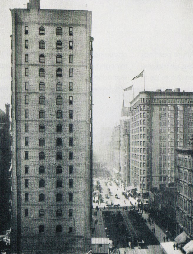
The facts are that the building’s structure is not a masonry wall, even though Root’s design made it “look” like a wall. Shepherd Brooks had denied the extensive use of iron framing in the building’s exterior, but this didn’t require the use of a brick wall. Architects had been designing buildings with masonry piers since the beginning of history, and the Monadnock Block was just one more example. This should be obvious when one looks at the building’s elevation: there is more void (the bay windows) in the building’s vertical surface than there is masonry.

Root never intended to express the structure in his final design of the Monadnock (other than in the placement of the windows: flush vs. deep). As I keep stating, there were more design concepts used by the Chicago School architects than only expressing the building’s structure. This is where the misunderstanding/misinterpretation of Root’s design begins. Even some contemporary critics, who now have a better understanding of the actual structure, fault Root for making the building look like a monolithic wall, when it is not one. They are still blinded by the “structural expression” mantra. Root had mastered the “structural expression” of the iron frame in the elevations of the Rookery’s lightcourt, and had already moved on to other design challenges. As was the case with the Rand-McNally Building, he was exploring the challenge of expressing the building’s skin/curtain wall as a continuous membrane or surface: he had already done so in the Rand-McNally’s 158’ long by 10-story high, unbroken surface of terra cotta, and would follow the Monadnock with a third iteration of the continuous skin in the Great Northern (Chicago) Hotel.

In his design for the Monadnock, he had accepted the office building’s function for this particular site: a ground floor hugging the lotlines, while the office floors were pulled back from the lotlines to be as efficient as possible. This established the building’s overall form. He then detailed the exterior surface as one continuous surface, as he had done in the Rand-McNally Building. The challenge for Root this time was that instead of the exterior being just a two-dimensional plane like the Rand-McNally, the Monadnock gave him the opportunity to extend the idea of the continuous surface over a three-dimensional form: he got to address the challenge in turning the corners of the building: i.e., avoiding a sharp edge to prevent the exterior from reading as two intersecting planes, so that one could perceive it only as a three-dimensional object. (Note that he used cylindrical bay windows to turn the corners in the Great Northern Hotel.) As he had done in his better designs, Root had chosen a leitmotif for the Monadmock: to lyrically recall (not copy) the form of the Egyptian pylon. With the addition of his plan to incorporate a gradation of color within the building’s exterior, he had designed not “just a building,” but, in the spirit of the great Wagner, a gesamtkunstwerk, that is, “a total work of architecture.”

FURTHER READING:
Hoffmann, Donald. The Architecture of John Wellborn Root. Baltimore: Johns Hopkins University Press, 1973.
Leslie, Thomas. Chicago Skyscrapers: 1871-1934. Urbana: University of Illinois, 2012.
Leslie, Thomas. “The Monadnock Building, Technically Reconsidered.” Council on Tall Buildings and Urban Habitat Journal, 2013 Issue IV.
(If you have any questions or suggestions, please feel free to eMail me at: thearchitectureprofessor@gmail.com)
